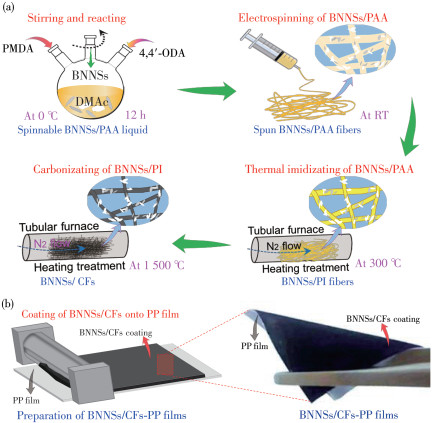
Figure 1.
(a) Synthetic route to BNNSs/CFs; (b) Schematic diagram of the preparation of BNNSs/CFs-PP films

Boron nitride nanosheets/carbon fibers-modified separators for high-performance lithium-sulfur batteries
He-Jun GAO , Jing-Wen YANG , Jia-Xiao QIAO , Wei QIAO , Chao-Chao CAO , Ze-Xia LI , Peng WANG , Cheng-Chun TANG , Yan-Ming XUE


The lithium- sulfur (Li-S) batteries have been regarded as one of the most possible energy storage sys- tems replacing current commercial lithium - ion batter- ies due to their high theoretical capacity (1 675 mAh· g-1) and energy density (2 600 Wh·kg-1) [1-3]. However, there are several challenges, such as the poor electrical conductivity of sulfur and Li2S/Li2 S2 producing after discharging process[4-5], the cathode volume expansion due to the different densities between sulfur and Li2S/ Li2S 2[6-7], and the"shuttle effect"of the soluble long - chain lithium polysulfides (LiPSs, Li2Sn, 4 ≤ n≤ 8) producing during charge/discharge process[8-9], which impede the practical development of Li - S batteries. Particularly, the shuttle effect of LiPSs is the main dis- advantage for damaging the cycle life and reducing the capacity of a Li-S battery.
Thus, many researchers have focused on modifier- modified separators to suppress the shuttle effect of Li - S cells. For example, activated carbon[10], reduced graphene oxide[11], carbon nanotube[12], and carbon nanofiber paper[13-14] are coated onto the separators for desired improvement of cell performance using their adsorption action to the LiPSs, due to larger specific surface area of these carbon-based modifiers. However, the weak interaction between non-polar carbon materials and the polar LiPSs cannot effectively confine the LiPSs migration. Thus, several polar materials, such as boron nitride[15-17], Mxene[18], and TiO2[19-20], are intro- duced into the separators. Due to the strong interaction between the LiPSs and these materials, the modified separators can effectively confine LiPSs to the cathode region. But this kind of polar material usually exhibits poor conductivity, which generally influences the elec- trochemical performance of Li -S batteries[21]. Thus, the composites consisting of polar boron nitride and carbon materials may be a kind of ideal modifiers to improve the separators, because they would have combined properties of good conductivity and favorite polar adsorption sites to the LiPSs.
In this work, the carbon fibers (CFs) were uniformly coated by boron nitride nanosheets (BNNSs) by combining electrospinning technology, thermal imidization, and carbonization processes, by using a spinnable liquid of polyamide acid (PAA) mixed with highly-functionalized BNNSs. Due to the formed CFs with highly polar surfaces made of the exposed BNNSs, the final modified layer of BNNSs/CFs composite coating not only has good conductive networks of CFs fibers but also shows a nice adsorption function of the LiPSs. Thus, this structure consisting of conductive fibers with polar surfaces can efficiently block the"shuttle effect" of the LiPSs. In addition, BNNSs/CFs can significantly promote the transport of lithium ions based on reducing the internal resistance of Li - S batteries. Therefore, BNNSs/CFs as the separation coating of Li - S battery significantly improves the rate performance and cycle performance of the battery. This study provides a rea- sonable design route to overcome the challenges of Li-S batteries in terms of shuttle effect and ion migration blockage, to promote the practical application of Li-S batteries.
The materials contained the commercial bulk hex- agonal boron nitride (h- BN) power with lateral size of ca. 10 µm, boric acid, 1, 2, 4, 5-benzenetetracarboxylic anhydride (PMDA, 99.0%), 4, 4′-diaminodiphenyl ether (4, 4′-ODA, 98.0%), N, N-dimthylacetamide (DMAc, 99.0%), N-methyl-2-pyrrolidone (NMP, 99.0%), polyvinylidene fluoride (PVDF, 99.5%), carbon black, lithium sulfide (Li2S), tetrahydrofuran (THF), and abso- lute alcohol. The electrolyte composed of 1 mol·L-1 bis (trifluoromethane) sulfonamide lithium salt (LiTFSI) in a mixed solvent of 1, 3-dioxolane (DOL) and 1, 2-dime- thoxyethane (DME) (volume ratio of 1∶1) with mass fraction of 1.0% LiNO3. These chemical reagents were used as received without any purification.
BNNSs were prepared by using our previous meth- od[22]. Typically, the commercial h-BN was corroded by boric acid by thoroughly mixing with the weight ratio of 1∶8 and heating at 200 ℃ for 24 h in an autoclave. Then, the obtained white block solid was ground into powder and put into ball - milling agate tanks for the mechanical - ball - milling exfoliation and functionaliza- tion of h - BN with a planetary ball- milling machine at 580r·min-1 for 48 h, to obtain ultrafine mixed powders. Then, the BNNSs product was gained after several deionized water scrubbing and centrifugation treatments, to completely remove the boric acid. Finally, a freeze-drying treatment was carried out to produce the pure BNNSs powder.
Firstly, 3.5 g of BNNSs powder was dispersed in 93 g of DMAc by stirring for 24 h to obtain the DMAc dispersion of BNNSs. After that, 15 g of 4, 4′-ODA was completely dissolved into this dispersion by stirring for 30 min. Subsequently, 16.5 g PMDA was equally divided into four parts and added into it for four times with 1 h as an interval time after each addition. After stirring for 12 h, a viscous BNNSs/PAA solution with different addition of BNNSs was achieved. All the stirring processes were in a dry three - neck round - bottom flask with continuous N 2 and ice bath by magnetic stirring. Due to the highly improving viscosity of the solution, the revolving speed was around 300 r·min-1 before and 100r·min-1 after adding all the PMDA. 10 mL of BNNSs/PAA solution was added into the syringe with a 20# gauge needle hole and installed in electrostatic spinning apparatus. The aluminum- foil- coated roller was the receiver and the distance between the needle and acceptant roller was 15 cm while opening the injection pump to inject. The spinning voltage was set at 18 kV and the spinning speed was 0.8 mL·h-1. Due to the poor stability of PAA[23], the sprayed fiber film was respectively heated at 80, 150, and 300 ℃ for 1, 2, and 2 h under a N2 gas atmosphere, to obtain boron nitride nanosheets/polyimide (BNNSs/PI) fiber film when it cooled naturally to room temperature. BNNSs/CFs were obtained after heating at 1 500 ℃ for 2 h under a N2 atmosphere. According to the different BNNSs contents in the BNNSs/PAA solution, BNNSs/CFs were named CFs (without any BNNSs), 5BNNSs/CFs (adding 5% BNNSs into the solution), 10BNNSs/CFs (adding 10% BNNSs into the solution), and 15BNNSs/CFs (adding 15% BNNSs into the solution), respectively.
BNNSs/CFs ink was prepared by mixing BNNSs/CFs material and PVDF binder with a weight ratio of 9∶ 1 and dispersing it into NMP solvent. Then, BNNSs/ CFs ink was coated on a commercial polypropylene (PP) separator of model Celgard 2325 by using a doctor blade with an average thickness of 200µm, to get a wet BNNSs/CFs - PP film. After a treatment dried at 50 ℃ under a vacuum overnight, the final BNNSs/CFs- PP film was formed, which was then cut into discs with a diameter of 19 mm as BNNSs/CFs-PP separators. By using the same method, the CFs - PP and BNNSs- PP separators were comparatively prepared.
According to the previous study[24-25], Li2S6 solution was prepared by dissolving Li2S and S8 into THF solvent with a molar ratio of 1∶5 and stirred at 60 ℃ for 12 h. According to the different concentration requests of adsorption and diffusion tests, some 2 and 5 mmol· L-1 Li2S6 solutions were separately made. These above experiments were carried out in an Ar-filled glove box.
To improve the conductivity of the cathode and avoid the break of the conductive matrix, the sulfur- containing cathode was prepared by mixing sulfur, car- bon black, and PVDF binder in NMP solvent with a weight ratio of 6∶3∶1. The slurry was uniformly coated on an aluminum foil, then dried at 60 ℃ under a vacuum for 12 h, which was then cut into discs with a diameter of 12 mm as cathodes. The areal densities of sulfur in the electrodes were 1.2-1.6 mg·cm-2.
The electrochemical properties of cells were tested by building the typical Li- S battery system. As shown in Fig.S1 (Supporting information), Li foils were used as the counter electrode towards the uncoated side of the separators and assembled into CR2032 coin cells with electrolyte. The cells were assembled in an Ar- filled glove box with moisture and oxygen contents less than 0.000 1%. Then, the galvanostatic charge - discharge measurements were conducted at a voltage interval of 1.7-2.8 V using a battery testing system (Land CT2001A). Especially, in the rate capability and cycling performance tests, cells needed to be precycled for three cycles at 0.05C (1C=1 675 mA·g-1) as activation. Cyclic voltammetry (CV) characterizations were performed on a CHI 760E electrochemical work- station at scanning rates of 0.2-0.5 mV·s-1 from 1.5 to 2.8 V. Electrochemistry impedance spectra (EIS) were carried out in the frequency range of 0.01-105 Hz.
The phases of materials were characterized by an X-ray diffractometer (XRD) (D8 Discover, Bruker, Germany) with the Cu Kα radiation (λ =0.154 nm). The working current was 20 mA and the working voltage was 36 kV with a 2θ range of 10°- 80°. The structures and morphologies of samples were analyzed by scanning electron microscopy (SEM, Quanta 450 FEG, FEI, USA) at 3-20 kV, with an energy- dispersive X-ray spec- trometer (EDS). The structures and morphologies of BNNSs were analyzed by a transmission electron microscopy (TEM, JEOL JEM 2100F, Japan) and a high- resolution TEM (HRTEM, JEOL JEM 2100F, Japan) with a resolution ratio of 0.2 nm. The BNNSs content of the sample was measured by a differential thermal and thermogravimetric analyzer (DT/TGA) (SDT Q-600, TA Instruments, USA) at a heating rate of 10 ℃ ·min-1 under air. And the chemical bonding and states of elements in materials were characterized by a Fourier transform infrared (FT - IR) (TENSOR 27, Bruker, Germany) at 4 000 to 400 cm-1 with the resolution ratio of 1 cm-1, and an X-ray Photoelectron spectroscopy analysis (XPS, ESCALAB 250Xi, Thermo Fisher Scien- tific, USA).
The synthetic route of BNNSs/CFs and the prepa- ration process of BNNSs/CFs- PP films are shown in Fig. 1. Due to the advantages of uniform lateral size, super-thin few-layer thickness, and rich-function level for as- exfoliated BNNSs, this BNNSs could be wellacted with PAA molecules in the DMAc solution, which can be easy to control to form a class of BNNSs/ PAA liquid with a spinnable viscosity (Fig. 1a). So, the BNNSs/PAA was well electrospun into fibrous morphology, to form the BNNSs/PAA fibers. After a thermal imidization performed on the BNNSs/PAA fibers at the final 300 ℃, the stable BNNSs/PI fibers with slightly shrunken diameters were produced, resulting in some BNNSs exposed to the fiber′s surfaces. After further carbonization process, the diameter of fibers decreased again, leading to much more BNNSs being exposed. Meanwhile, the final mass ratio of BNNSs in the 10BNNSs/CFs was determined to be 37.59% by calculating from the TGA data (Fig.S2), which indicated lots of mass loss occurred in thermal imidization and car- bonization processes from the initial BNNSs/PAA converted to the final BNNSs/CFs products. Based on the natural properties of intercrossing stacking networks formed easily by fiber-like morphology, the fibrous BNNSs/CFs assisted with PVDF binder would be properly and compactly coated onto commercial PP film, to make a kind of BNNSs/CFs - PP composite film with favorite flexibility and strong inter-adhesion (Fig. 1b).
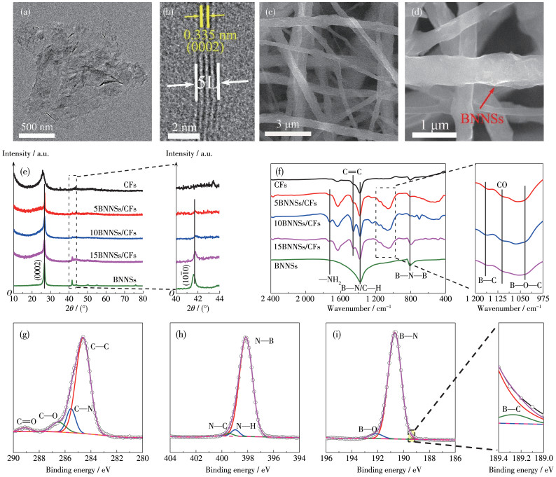
The detailed characteristics of the BNNSs, BNNSs/CFs, and CFs materials were carried out using TEM, SEM, XRD, FT-IR, and XPS technologies (Fig. 2 and Fig.S3-S5). By using the boric acid-assisted chemo - mechanical exfoliation, the obtained BNNSs powders have a decreased lateral size of ca. 1 000 nm (Fig. 2a) but possess an ultra-thin thickness of few-layer stacking (0002) planes of h- BN (several layers planes fre- quently observed in HRTEM, Fig. 2b). Benefitting from the especial morphology and structure of BNNSs powders, the fibrous morphology of BNNSs/CFs could be well maintained after the thermal imidization and high- temperature carbonization (Fig. 2c, 2d). It is found that lots of BNNSs were exposed on the fiber′s surfaces (Fig. 2d). Due to the addition of BNNSs, the larger diam- eter and more uniform distribution of 10BNNSs/CFs was created in the well - hybridized BNNSs/CFs fibers (Fig. S3). In the XRD patterns, except for the typical (0002) (at ca. 26.8°), (1010) (located at 41.7°) plane diffractions of the BNNSs, an emerged broad peak at around 26° was attributed to the (0002) diffraction pat- tern of carbon from CFs (Fig. 2e). Such fact combined with a slightly decreased intensity of the diffraction at 41.7° with a decrease in BNNSs contents suggests a well intrinsic h - BN nature of BNNSs maintained into BNNSs/CFs. Due to the existence of BNNSs in the car- bonization process, several extra FT-IR peaks at 1 166, 1 111, and 1 035 cm-1 corresponded to the B—C, CO, and B—O—C vibrations for 5 BNNSs/CFs, 10 BNNSs/ CFs, and 15BNNSs/CFs, indicating a formation of strongly covalent - bonding interaction between BNNSs and CFs (Fig. 2f) [26-27]. Also, the high- resolution C1s, N1s, and B1s XPS spectra with the coexistence of the nicely fitted C—C, C—N, C—O, C=O, N—B, N—H, N—C, B—C, B—N, and B—O chemical bonding imply a strongly interconnected interface between BNNSs and CFs (Fig. 2g-2i)[19, 23, 28-31].
Due to the well-hybridized combination of BNNSs and CFs within BNNSs/CFs, the Li - S cells assembled with the 10BNNSs/CFs - PP separators could exhibit a more excellent electrochemical performance than that encapsulated with single BNNSs - or CFs - modified PP separators and the blank PP separator (Fig. 3). The diameter of the medium - to - high frequency semicircle of Nyquist plots represented the charge transfer resistance (Rct) (Fig. 3a)[32]. The Nyquist plot of the uncycled Li - S cell assembled with 10BNNSs/CFs- PP separator had a resistance value, estimated to be ca. 25 Ω, only slightly larger than that with the CFs-PP separator (ca. 10 Ω). This is because there has a strongly hybridized combination between CFs and BNNSs in 10BNNSs/ CFs, in which, the BNNSs parts have a relatively lower conductivity. The Rct value for the 10BNNSs/CFs - PP cell was much lower than that of the pristine PP cell (ca. 80 Ω) and BNNSs-PP cell (ca. 60 Ω). This is due to that the main CFs parts within BNNSs/CFs fibers enable a highly efficient conductive pathway for electrons and Li+ ions, which could provide transfer channels for electrons and Li+ ions[33-35], and electrons are from the cathode closely contacting to the 10BNNSs/ CFs coating layer in the cell.
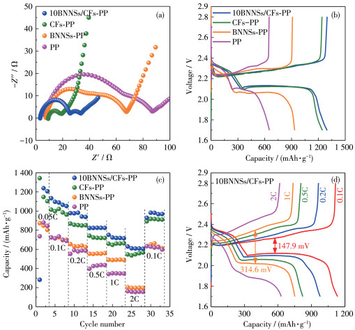
The capacity performances of these Li-S cells assembled with different separators were measured by the galvanostatic charge - discharge tests in the voltage range from 1.7 to 2.8 V at 0.05C (Fig. 3b). The higher plateau at around 2.35 V in the discharge profile was associated with a soluble long- chain LiPSs formation, and another discharge plateau near 2.1 V was associated with further conversion of the LiPSs to the insoluble Li2S2/Li2S[36]. Besides, the two charge plateaus near 2.35 and 2.40 V corresponded to the oxidization reactions of Li2S2/Li2S to the LiPSs and the LiPSs to S8, respectively[37]. Assembled with the 10BNNSs/CFs - PP separator, the initial discharge capacity of the cell was shown as 1 295.7 mAh·g-1, which was much larger than that with the CFs-PP (1 244.4 mAh·g-1), BNNSs- PP (934.1 mAh·g-1), and PP (651.2 mAh·g-1) separators. In addition, the increased capacity of the 10BNNSs/CFs-PP-made cell mainly came from the second discharge plateau, which indicated that 10BNNSs/ CFs could effectively promote the reduction capacity of the solid-phase reaction of the LiPSs to Li2S. This high- er capacity was attributed to the high polarity located on the BNNSs - exposed surfaces of BNNSs/CFs, which can restrict the shuttle effect of soluble LiPSs towards the Li anode.
The rate capability of the batteries assembled with different separators evaluated at different current densities from 0.1C, 0.2C, 0.5C, 1C to 2C and returning to 0.1C was tested (Fig. 3c). The cell assembled with the 10BNNSs/CFs-PP separator expressed excellent specific capacities higher than the CFs-PP, BNNSs-PP, and PP separators at various current densities. At a high cycling rate of 2C, the first capacity of the 10BNNSs/CFs- PP cell was about 629.7 mAh·g-1, which could keep it much more stable for five cycles. In contrast, the PP, BNNSs-PP, and CFs-PP separators cases only reached 162.2, 204.1, and 546.5 mAh·g-1 at 2C, respectively.When the current density returned to 0.1C, the capaci- ty of 10BNNSs/CFs- PP cell could back to the 982.6 mAh·g-1, which was much higher than that with CFs - PP (918 mAh·g-1), BNNSs - PP (651.3 mAh·g-1), and PP (627.7 mAh·g-1) separators.
The initial charge - discharge curves at different current densities also confirmed the stable electrochemical performance of 10BNNSs/CFs - PP cells (Fig. 3d and Fig. S6). The 10BNNSs/CFs - PP cell had the smallest separations between its second discharge platform and charge platform (Fig. 3d), compared with the CFs-PP, BNNSs-PP, and PP separator-made cells (Fig.S6). At 0.1C, the separation value of the cell with the 10BNNSs/CFs - PP separator was 147.9 mV, lower than the CFs - PP (163.7 mV), BNNSs- PP (184.1 mV), and PP (156.0 mV) separators. Especially at a high current density of 1C, the separation value with the 10BNNSs/CFs-PP separator (314.6 mV) was much low- er than the CFs - PP (344.2 mV), BNNSs- PP (420.3 mV), and PP (414.6 mV) separators. These results sug- gested the smallest loss of active substance during the charge - discharge conversion, using BNNSs/CFs coat- ing modification onto the PP separator within the Li-S cells.
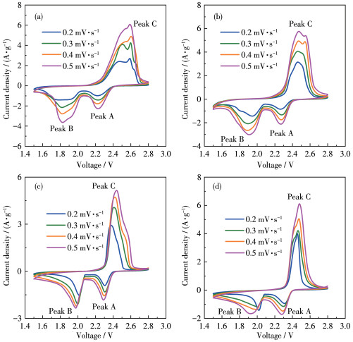
A series of CV curves at the scanning rates of 0.2 to 0.5 mV·s-1 and the corresponding fitted linear rela- tionship of their peak current densities vs square root of scanning rate used were plotted to further demon- strate the influence of the 10BNNSs/CFs - PP separator on the dynamically electrochemical performance the cells (Fig. 4 and 5). There were several redox peaks in the CV curves of cells assembled with 10BNNSs/CFs - PP, CFs-PP, BNNSs-PP, and PP separators. The reduction peak A ranging from 2.2 to 2.3 V was connected with the higher discharge plateau, and the reduction peak B inhabited from 1.8 to 2.0 V was associated with the lower discharge plateau (Fig. 3b). Besides, the oxidation peak C located between 2.4 to 2.6 V was attributed to the reverse reactions of Li2S2/Li2S to the final S8. Particularly, there were two much more obvious oxida- tion peaks in the curves of the cell assembled with the 10BNNSs/CFs - PP separator compared with the cases of the CFs - PP, BNNSs - PP, and the blank PP, which were generated from the two charge plateaus of the oxidization reactions of Li 2S2 /Li2S to the LiPSs and the LiPSs to S8 (Fig. 4). Due to that the restriction action of the LiPSs"shuttle effect"on the 10BNNSs/CFs - PP separator is more efficient than that on the CFs-PP and BNNSs - PP separators, the oxidization peak located at higher voltage was enhanced, which indicate more LiPSs-to-S8 reaction emerged during cells′ cycles.
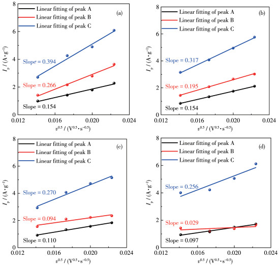
In addition, the values of the diffusion coefficient of the Li+ ions can be calculated using the Randles - Sevcik equation: Ip = (2.69×10⁵)n1.5ADLi0.5cLiv0.5, where Ip is the peak current density, n is the number of elec- trons transferred in the charging process, A is the surface area of the active electrode, DLi is the values of the diffusion coefficient of the Li+ ions, cLi is the concentration of Li+ in the electrolyte, and v is the scan rate. Thus, the slope of the linear plot of Ip versus the square root of the scan rate (v0.5) could reflect the diffusion coefficient of the Li+ ion (Fig. 5). The slopes of the cell assembled with the 10BNNSs/CFs - PP separator were 0.154, 0.266, and 0.394 for peaks A, B, and C, respectively. These values were much higher than those with PP (0.097, 0.029, and 0.256), BNNSs - PP (0.110, 0.094, and 0.270), and CFs- PP (0.154, 0.195 and 0.317) separators, respectively. In addition, the areas of CV curves of cells with 10BNNSs/CFs-PP separators were higher than that of the cells with PP, BNNSs-PP, and CFs - PP separators, meaning the highest charge - discharge capacity as well as its cycle stability (Fig. S7) [38]. Thus, these 10BNNSs/CFs - modified PP films would be used as a kind of ideal separator material for Li-S cells.
The cells assembled with 10BNNSs/CFs-PP, CFs- PP, BNNSs - PP, and PP separators exhibited different cycling performances at current densities of 0.2C, 0.5C, and 1C (Fig. 6), which displays that the cells assembled with the 10BNNSs/CFs- PP separator showed the highest discharge capacities and favorable cycling stabilities. These cells could deliver an initial discharge capacity of 1 080.8 mAh·g-1 under 0.2C, and stably retain the discharge capacity of 914.7 mAh·g-1 after 100 cycles. In contrast, the cells assembled with CFs - PP, BNNSs - PP, and PP separators could merely deliver 707.8, 515.6, and 445.4 mAh·g-1 after 100 cycles under the same current density, respectively. At the rate of 0.5C, the cell assembled with the 10BNNSs/ CFs-PP separator still showed outstanding cycle stability with a capacity decay of only 0.16% per cycle and a capacity of 813.1 mAh·g-1 was well retained after 100 cycles. Such capacity was also higher than those assembled with CFs- PP, BNNSs- PP, and PP separators, which were 576.2, 379.4, and 285.3 mAh·g-1, respectively. These results were caused by the well - hybrid- ized BNNS-CFs- bonded structures that led to their better adsorption of the LiPSs and inhibition of the" shuttle effect", which could significantly change the morphology of separators after cycling (Fig.S8).

Furthermore, the cell assembled with the 10BNNSs/CFs-PP separator also showed excellent cycling stability at 1C, which attained a discharge capacity of 583.1 mAh·g-1 after 400 cycles with a capacity decay of 0.069% per cycle (Fig. 6b). As a contrast, there was only 159.5 mAh·g-1 with a higher capacity decay of 0.181% per cycle after 400 cycles for the cell assembled with the CFs - PP separator. The cells assembled with BNNSs-PP and PP separators had bad performances at a high current density of 1C, which had only about 150 mAh·g-1 for all 400 cycles. The excellent long -cycle stability of Li-S cells assembled with the 10BNNSs/CFs- PP separator should be attributed to the excellent conductive network of CFs parts and the powerful polar absorption ability to the LiPSs and confined them in the cathode region due to the BNNSs parts.
Compared with those of the separators modified by other materials (Table S1), the electrochemical properties of the Li - S cells made by 10BNNSs/CFs - modified - PP separators were very superior. For example, the performance of 10BNNSs/CFs - PP - assembled cells was very close to that of the current advanced Li - S batteries assembled with RGA - ZnS/PP separator produced by Liu et al.[39], which could deliver an initial capacity of 800 mAh·g-1 and a capacity of 407 mAh· g-1 after 500 cycles under 1C with a sulfur loading of ca. 1.5 mg·cm-2. In addition, the cells assembled with MPF13 - 550/PP separator produced by Lin et al. [40] could attain an initial charge capacity of 781 and 445 mAh·g-1 after 200 cycles under 1C with a sulfur loading of 1.2 - 1.6 mg·cm-2, which was lower than that of the cells made by this work.
The excellent electrochemical properties of the cells with the 10BNNSs/CFs - PP separator were attributed to the dominant LiPSs adsorption function of 10BNNSs/CFs, which can efficiently restrict the shuttle effect of the LiPSs during the cell′s charge/discharge process (Fig. 7, S9). Due to the adsorption of 10BNNSs/ CFs to Li2S6, the coating of BNNSs/CFs onto the PP to form the composite film also exhibited excellent restric- tion action of permeability of Li2S 6 (Fig. 7). To demonstrate the restriction action of the LiPSs shuttle effect of the 10BNNSs/CFs - PP separator, the LiPSs permeation tests were achieved via special diffusion bottles. The internal container was packed with 2 mL of Li2S6 in THF (5 mmol·L-1), and the external container was packed with 10 mL of pure THF. These two containers were separated by 10BNNSs/CFs-PP, CFs-PP, and PP separators in the white cap, having a hole, in the internal container, respectively. Thus, this hole covered by the different separators was the only passway between the inner and outer containers. The color change of the solution in the external container indicates the diffusion behavior of Li 2S6. The final result is shown in Fig. 7, the external container gradually turns yellow- brown after 20 h in the case of the PP separator. There was also a significant color change after 45 h in the case of the CFs - PP separator. In addition, no obvious color change was observable by using the 10BNNSs/ CFs- PP separator after 45 h, although the electrolyte wettability for the BNNSs/CFs coating was better than that of the CFs coating, BNNSs coating, and the blank PP (Fig.S9b-S9e). Thus, the two series of experimental results indirectly suggested that the BNNSs/CFs- modified separators fulfilled a key role in mitigating the LiPSs shuttle effect within Li-S cells.

In summary, we prepared a functional separator for Li- S batteries by simply coating a thin film of composite fibers, which were the carbon fibers combined with boron nitride nanosheets, on the separator. Cycled at 0.05C, the cell with a 10BNNSs/CFs separator exhibited a high initial capacity of 1 295.7 mAh·g-1. Cycled at 1C, the cells still maintained a reversible capacity of 583.1 mAh·g-1 after 400 cycles with a capacity decay of 0.069% per cycle. While BNNSs sufficiently provided to trap the LiPSs, the network of CFs provided a conductive path for the charge - discharge process. Thus, the well - hybridized combination of 10BNNSs/CFs could significantly mitigate the shuttle effect by localizing the soluble LiPSs within the cathode region, leading to low active sulfur loss and enhanced cycle stability. The facile strategies of this modified separator can be conducive to the large-scale commercialization of Li-S batteries.
Supporting information is available at
Bu F X, Shakir I, Xu Y X. 3D graphene composites for efficient electrochemical energy storage[J]. Adv.Mater. Interfaces, 2018, 5(15): 1800468. doi: 10.1002/admi.201800468
Manthiram A, Fu Y Z, Su Y S. Challenges and prospects of lithium-sulfur batteries. Acc[J]. Chem. Res, 2013, 46(5): 1125-1134. doi: 10.1021/ar300179v
Deng N P, Liu Y, Li Q X, Yan J, Lei W W, Wang G, Wang L Y, LiangY Y, Kang W M, Cheng B W. Functional mechanism analysis and customized structure design of interlayers for high performance Li-S battery[J]. Energy Storage Mater, 2019, 23: 314-349.
王相文. 层状六边形Co1-xS修饰氮掺杂碳纳米管用于锂硫电池的硫载体[J]. 无机化学学报, 2022,38,(10): 2065-2071. doi: 10.11862/CJIC.2022.180WANG X W. Layered hexagonal Co1-xS decorating N - doped carbon nanotubes as a sulfur host for Li-S batteries[J]. Chinese J. Inorg. Chem, 2022, 38(10): 2065-2071. doi: 10.11862/CJIC.2022.180
Ni L B, Yang G, Liu Y, Wu Z, Ma Z Y, Shen C, Lv Z X, Wang Q, Gong X X, Xie J, Diao G W, Wei Y G. Self-assembled polyoxometalate nanodots as bidirectional cluster catalysts for polysulfide/sulfide redox conversion in lithium-sulfur batteries[J]. ACS Nano, 2021, 15(7): 12222-12236. doi: 10.1021/acsnano.1c03852
潘沛锋, 陈平, 方亚男, 单淇, 陈宁娜, 冯晓苗, 刘瑞卿, 李盼, 马延文. V2O5空心球作为高效硫载体用于锂硫电池[J]. 无机化学学报, 2020,36,(3): 575-583. PAN P F, CHEN P, FANG Y N, SHAN Q, CHEN N N, FENG X M, LIU R Q, LI P, MA Y W. V2O5 hollow spheres as high efficient sulfur host for Li-S batteries[J]. Chinese J. Inorg. Chem, 2020, 36(3): 575-583.
Yamamoto, Goto, Tang, Nomura, Hayasaka, Yoshioka, Ito, Morooka, Nishihara, Kyotani, T. Nano - confinement of insulating sulfur in the cathode composite of all-solid-state Li-S batteries using flexible carbon materials with large pore volumes[J]. ACS Appl. Mater. Interfaces, 2021, 13(32): 38613-38622. doi: 10.1021/acsami.1c10275
Ponnada S, Kiai M S, Gorle D B, Rajagopal S, Andra S, Nowduri A, Muniasamy K. Insight into lithium- sulfur batteries with novel modified separators: recent progress and perspectives[J]. Energy & Fuels, 2021, 35(14): 11089-11117.
李锐, 孙晓刚, 邹婧怡, 何强. NMAP夹层抑制锂硫电池穿梭效应[J]. 无机化学学报, 2020,36,(4): 673-680. LI R, SUN X G, ZOU J Y, HE Q. NMAP interlayer for inhibiting shuttle effect of lithium-sulfur battery[J]. Chinese J. Inorg. Chem, 2020, 36(4): 673-680.
Yang T, Song Y, Tian X D, Wu S J, Liu Z J. Insight into pore structures evolution and applications in lithium - sulfur battery of pitch fractions - based activated carbons[J]. J. Alloy. Compd, 2021, 875: 160067. doi: 10.1016/j.jallcom.2021.160067
Xiao H, Zhang T F, Liang X, Gao Q M. A porous rGO with high specific surface area and high content of doped-N modifying the separator for high performance Li-S battery[J]. Electrochim. Acta, 2021, 391: 138910. doi: 10.1016/j.electacta.2021.138910
朱绍宽, 宋娅, 龙翔, 欧阳全胜, 邵姣婧, 石斌. 镧掺杂锡酸钡/多壁碳纳米管改性隔膜的制备及其在锂硫电池中的应用[J]. 无机化学学报, 2022,38,(7): 1433-1440. ZHU S K, SONG Y, LONG X, OUYANG Q S, SHAO J J, SHI B. La-doped BaSnO3/multi-walled carbon nanotube modified separator: Synthesis and application in lithium-sulfur battery[J]. Chinese J. Inorg. Chem, 2022, 38(7): 1433-1440.
Chung S H, Han P, Singhal R, Kalra V, Manthiram A. Electrochemically stable rechargeable lithium-sulfur batteries with a microporous carbon nanofiber filter for polysulfide[J]. Adv. Energy Mater, 2015, 5(18): 1500738. doi: 10.1002/aenm.201500738
Yang T, Tian X D, Song Y, Wu S J, Liu Z J. Oxygen-doped carbon nanofiber nonwovens as an effective interlayer towards accelerating electrochemical kinetics for lithium - sulfur battery[J]. Appl. Surf. Sci, 2023, 611: 155690. doi: 10.1016/j.apsusc.2022.155690
Kim P J H, Seo J, Fu K, Choi J, Liu Z M, Kwon J, Hu L B, Paik U. Synergistic protective effect of a BN-carbon separator for highly stable lithium sulfur batteries[J]. NPG Asia Mater, 2017, 4(e375): .
Huang W L, Wang P Y, Liao X B, Chen Y J, Borovilas J, Jin T W, Li A J, Cheng Q, Zhang Y F, Zhai H W, Chitu A, Shan Z Q, Yang Y. Mechanically-robust structural lithium-sulfur battery with high energy density[J]. Energy Storage Mater, 2020, 33(416): 422.
Fan Y, Yang Z, Hua W X, Liu D, Tao T, Rahman M M, Lei W W, Huang S M, Chen Y. Functionalized boron nitride nanosheets/graphene interlayer for fast and long-life lithium-sulfur batteries[J]. Adv. Energy Mater, 2017, 7(13): 1602380. doi: 10.1002/aenm.201602380
Song J J, Su D W, Xie X Q, Guo X, Bao W Z, Shao G J, Wang G X. Immobilizing polysulfides with MXene-functionalized separators for stable lithium-sulfur batteries[J]. ACS Appl. Mater. Interfaces, 2016, 8(43): 29427-29433. doi: 10.1021/acsami.6b09027
Gui Y Y, Chen P, Liu D Y, Fan Y, Zhou J, Zhao J X, Liu H, Guo X, Liu W Q, Cheng Y. TiO2 nanotube/RGO modified separator as an effective polysulfide - barrier for high electrochemical performance Li-S batteries[J]. J. Alloy. Compd, 2021, 895: 162495.
Jiao L, Zhang C, Geng C N, Wu S C, Li H, Lv W, Tao Y, Chen Z J, Zhou G M, Li J, Ling G W, Wan Y, Yang Q H. Capture and catalytic conversion of polysulfides by in situ built TiO2-MXene heterostructures for lithium-sulfur batteries[J]. Adv. Energy Mater, 2019, 9(19): 1900219. doi: 10.1002/aenm.201900219
Wei Z H, Ren Y Q, Sokolowski J, Zhu X D, Wu G. Mechanistic understanding of the role separators playing in advanced lithium-sulfur batteries[J]. InfoMat, 2020, 2(3): 483-508. doi: 10.1002/inf2.12097
Zhai Q H, Yang J W, Quo W, Quo J X, Gao H J, Li Z X, Wang P, Tang C C, Xue Y M. Ultralight and highly resilient boron nitride nanosheet/polyimide foams for energy harvesting and sensing[J]. ACS Appl. Polym. Mater, 2022, 4(5): 3236-3246. doi: 10.1021/acsapm.1c01795
Reynolds R J W, Seddon J D. Amine salts of polypyromellitamic acids[J]. J. Polym. Sci, 1968, C23: 45-56.
Bieker G, Wellmann J, Kolek M, Jalkanen K, Winter M, Bieker P. Influence of cations in lithium and magnesium polysulphide solutions: Dependence of the solvent chemistry[J]. Phys. Chem. Chem. Phys, 2017, 19(18): 11152-11162. doi: 10.1039/C7CP01238A
Qiu W J, An C H, Yan Y W, Xu J, Zhang Z J, Guo W, Wang Z, Zheng Z J, Wang Z B, Deng Q B, Li J S. Suppressed polysulfide shuttling and improved Li+ transport in Li- S batteries enabled by NbN modified PP separator[J]. J. Power Sources, 2019, 423: 98-105. doi: 10.1016/j.jpowsour.2019.03.070
Mondal S, Banthia A K. Low-temperature synthetic route for boron carbide[J]. J. Eur. Ceram. Soc, 2005, 25(2/3): 287-291.
Ghanbarian M, Nassaj E T, Kariminejad A. Synthesis of nanostructural turbostratic and hexagonal boron nitride coatings on carbon fiber cloths by dip-coating[J]. Surf. Coat. Technol, 2016, 288: 185-195. doi: 10.1016/j.surfcoat.2016.01.011
Kim E, Kim J, Lee T, Kang H, Yu S, Park J W, Lee S G, Li O L, Lee J H. Plasma - engineered organic dyes as efficient polysulfide - mediating layers for high performance lithium-sulfur batteries[J]. Chem. Eng. J, 2022, 430: 132679. doi: 10.1016/j.cej.2021.132679
Zhang T, Zhang J, Wen G W, Zhong B, Xia L, Huang X X, Zhao H, Wang H T, Qin L C. Ultra-light h-BCN architectures derived from new organic monomers with tunable electromagnetic wave absorption[J]. Carbon, 2018, 136: 345-358. doi: 10.1016/j.carbon.2018.05.001
Guan C Y, Zhao J J, Jia F C, Zhuang C Q, Bai Y Z, Jiang X. Relationship between chemical compositions of magnetron sputtered B-C-N films and various experimental parameters[J]. Vacuum, 2012, 86(10): 1499-1504. doi: 10.1016/j.vacuum.2012.03.013
Das M, Basu A K, Ghatak S, Joshi A G. Carbothermal synthesis of boron nitride coating on PAN carbon fiber[J]. J. Eur. Ceram. Soc, 2009, 29(10): 2129-2134. doi: 10.1016/j.jeurceramsoc.2008.12.004
邵智韬, 武立立, 杨月, 马新志, 李璐, 叶红凤, 张喜田. 碳纳米管承载MoSe2纳米片作为锂硫电池的夹层材料[J]. 新型碳材料, 2021,36,(1): 219-225. SHAO Z T, WU L L, YANG Y, MA X Z, LI L, YE H F, ZHANG X T. Carbon nanotube-supported MoSe2 nanoflakes as an interlayer for lithium-sulfur batteries[J]. New Carbon Materials, 2021, 36(1): 219-225.
张梦源, 游小龙, 刘丽君, MaruDessie Walle, 李亚娟, 刘又年. 基于生物质的高度有序的管状碳材料及其在锂硫电池中的应用[J]. 无机化学学报, 2019,35,(8): 1493-1499. ZHANG M Y, YOU X L, LIU L J, MARU D W, LI Y J, LIU Y N. Biomass derived highly-ordered carbon tube as cathode material for high performance lithium-sulfur batteries[J]. Chinese J. Inorg. Chem, 2019, 35(8): 1493-1499.
Zhou X Y, Liao Q C, Tang J J, Bai T, Chen F, Yang J. A high-level N - doped porous carbon nanowire modified separator for long - life lithium-sulfur batteries[J]. J. Electroanal. Chem, 2016, 768: 55-61.
Yang S N, Cheng Y, Xiao X, Pang H. Development and application of carbon fiber in batteries[J]. Chem. Eng. J, 2020, 384: 123294.
毛艳, 张传辉, 张洋, 王琪, 徐桂良, 黄令, 李君涛, 孙世刚. 锂硫电池膨胀氧化石墨/硫复合正极材料的制备及其性能[J]. 无机化学学报, 2013,29,(5): 889-895. MAO Y, ZHANG C H, ZHANG Y, WANG Q, XU G L, HUANG L, LI J T, SUN S G. Synthesis and electrochemical performance of novel expanded graphite oxide/sulfur composite cathodes for lithium-sulfur batteries[J]. Chinese J. Inorg. Chem, 2013, 29(5): 889-895.
Li Y J, Fan J M, Zhang J H, Yang J F, Yuan R M, Chang J K, Zheng M S, Dong Q F. A honeycomb-like Co@N-C composite for ultrahigh sulfur loading Li-S batteries[J]. ACS Nano, 2017, 11(11): 11417-11424.
Zhang Z Y, Yi S, Wei Y J, Bian H Y, Wang R B, Min Y G. Lignin nanoparticle-coated celgard separator for high-performance lithium-sulfur batteries[J]. Polymers, 2019, 11(12): 1946.
Liu Z E, Hu Z W, Jiang X A, Zhang Y, Wang X W, Zhang S G. Multi-functional ZnS quantum dots/graphene aerogel modified separator for high performance lithium - sulfur batteries[J]. Electrochim. Acta, 2022, 422: 14096.
Lin L W, Qi M, Bai Z T, Yan S X, Sui Z Y, Han B H, Liu Y W. Crumpled nitrogen-doped aerogels derived from MXene and pyrrole-formaldehyde as modified separators for stable lithium-sulfur batteries[J]. Appl. Surf. Sci, 2021, 555: 149717.

Figure 1 (a) Synthetic route to BNNSs/CFs; (b) Schematic diagram of the preparation of BNNSs/CFs-PP films

Figure 2 Characteristics of the materials: (a, b) TEM and HRTEM images of BNNSs; (c, d) SEM images of 10BNNSs/CFs; (e) XRD patterns and the corresponding enlarged patterns of CFs, 5BNNSs/CFs, 10BNNSs/CFs, 15BNNSs/CFs, and BNNSs; (f) FT⁃IR spectra of CFs, 5BNNSs/CFs, 10BNNSs/CFs, 15BNNSs/CFs, and BNNSs and the corresponding enlarged spectra from 1 200 to 975 cm-1; (g) C1s, (h) N1s, and (i) B1s XPS spectra of 10BNNSs/CFs and the corresponding enlarged spectra

Figure 3 Electrochemical performances of Li-S batteries assembled with different separators of 10BNNSs/CFs-PP, CFs-PP, BNNSs⁃PP, and blank PP: (a) Nyquist plots of the as⁃formed Li-S batteries; (b) initial galvanostatic charge-discharge profiles of these batteries operated with an identical current density of 0.05C; (c) rate capability of these cells; (d) relative galvanostatic charge-discharge curves of the cell with the 10BNNSs/CFs⁃PP separator at different densities from the corresponding data in (c)

Figure 4 CV curves at 0.2, 0.3, 0.4, and 0.5 mV·s-1 of cells assembled with 10BNNSs/CFs-PP (a), CFs-PP (b), BNNSs⁃PP (c), and PP (d) separators

Figure 5 Corresponding Ip vs v0.5 plots of the cells assembled with 10BNNSs/CFs-PP (a), CFs-PP (b), BNNSs-PP (c), and PP (d) separators

Figure 6 (a) Cycling performance of the cells assembled with 10BNNSs/CFs-PP, CFs-PP, BNNSs-PP, and PP separators at 0.2C and 0.5C; (b) Long-cycling performance of the cells assembled with above four separators at 1C

 扫一扫看文章


扫一扫关注我们
 下载:
下载:
 下载:
下载:
