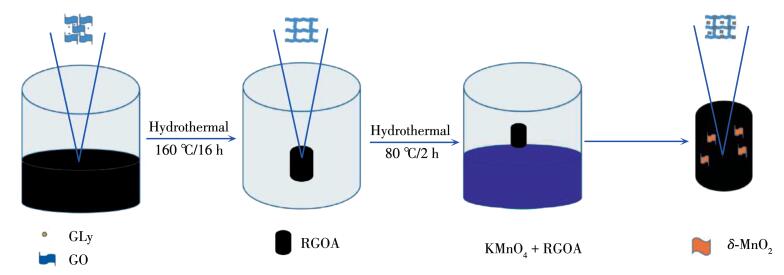
Scheme 1.
Schematic illustration on preparation process of RGOA/δ-MnO2 composite
Preparation and Electrochemical Performance of δ-MnO2/Graphene Aerogels For Li-Ion Batteries
Zhi LI , Xiao HUANG , Xiu-Quan GU , Zheng XING , Yu-Long ZHAO , Ying-Huai QIANG

As a promising energy storage technology for consumer electronics, electric vehicles, and stationary energy storage systems, rechargeable lithium - ion batteries (LIBs) have been widely studied owing to their high energy density, long cycle life, and low cost[1]. Nevertheless, the commercial graphite anodes still have a low theoretical specific capacity (< 360 mAh·g-1) and rate performance, which is a challenge to meet the everincreasing power demand and higher energy density.
Graphene, a single layer of sp2 - hybridized in a hexagonal honeycomb lattice, has received persistent attention due to its unique electrical, mechanical, and thermal properties. For the LIB application, the theoretical capacity of graphene can reach up to 744 mAh·g-1 due to the formation of a Li3C structure[2]. Very recently, it was revealed that the assembly of two - dimensional (2D) graphene sheets into three-dimensional (3D) architectures can provide resultant graphene-based composites with stronger mechanical strengths[3], lighter weight, and more rapid electron transport kinetics[4].
So far, a number of researches have been focused on developing high-capacity and long cycle life anodes, such as carbonaceous materials, conducting polymers, and transition metal oxides (TMOs) [5-6]. As a usual TMO, δ-MnO2 has been used widely as the LIB anode for its high capacity, low cost, environmental friendliness, and natural abundance[7-8]. However, the charge transfer in a common δ - MnO2 anode is hindered by both inherently poor electrical conductivity and ionic conductivity. The common δ - MnO2 anode also suffers severe volume expansion (>300%) during the Li-ion insertion process, and undesired aggregation of particles and formation of thick solid electrolyte interphase (SEI) layer during the discharge - charge cycling process[9]. Therefore, it is necessary to combine the advantages of δ - MnO2 nanoparticles (NPs) and reduced graphene oxide aerogel (RGOA) in order to boost the conductivity, as well as to relieve the aggregation and reduce the volume expansion of TMO anodes. To the best of our knowledge, there have been no any reports on the electrochemical performance of 3D network RGOA/δ-MnO2 anodes.
Currently, there are two types of electrochemical energy storage devices: LIB and supercapacitor. The LIB owns a large energy density but a slow charge rate, while the supercapacitor displays the merits of fast charging and long-term cycling stability but low energy density. Apparently, they also work in different mechanisms: the LIB is dominated by a diffusion - controlled process because the Li ion diffusion rate is much lower than the charge transfer rate, while the supercapacitor follows a pseudocapacitive - controlled mechanism due to the typical ionic absorption effect. Currently, it is necessary to increase the pseudocapacitive contribution of LIBs in order to satisfy the requirements of a fast charging vehicle.
In this research, a simple self-assembly route was developed to synthesize the RGOA/δ-MnO2 hybrids for the LIB applications, where the ultrathin δ-MnO2 nanosheets (NSs) were successfully integrated into the RGOA. The effect of δ-MnO2 content on the device performance was investigated systematically. After constructing a LIB, the specific capacity of the RGOA anode can be significantly improved from 720.8 to 1 701.9 mAh·g-1 by incorporating a suitable quantity of δ - MnO2 NPs. The excellent performance of RGOA/δ-MnO2-160 mg can be attributed to both the high theoretical capacity of MnO2, rapid Li - ion transport channel and charge transport network of RGOA. Additionally, the pseudocapacitive contribution cann′t be neglected, and it would be helpful for achieving a good rate performance.
Hydrogen peroxide (H2O2, 30%, w/w, AR), hydrochloric acid (HCl, 36%~38%, AR), potassium permanganate (KMnO4, ≥99.5%), natural graphite (99%), anhydrous sodium nitrate (NaNO3, ≥99.5%), concentrated sulfuric acid (H2SO4, 96%~98%, AR). Glycine (Gly) was purchased from Aladdin Chemical (Shanghai, China).
Briefly, the reduced graphene oxide (RGO) was prepared from natural graphite flakes through the modified Hummers method[10]. First, 70 mL H2SO4 was poured into a 1 000 mL beaker and then placed in an ice bath. Afterward, NaNO3 (0.5 g) and natural graphite (1.0 g) were slowly added into the above solution and stirring for 20 min. Finally, KMnO4 (5 g) was slowly added into the beaker and kept in an ice bath environment for 12 h, which was followed by a dilution process with a large amount of deionized (DI) water. After cooling to room temperature (RT), HCl (10 mL) and H2O2 (10 mL) were sequentially added to the above solution until appearing a bright yellow color. Afterward, the obtained products were naturally precipitated and washed several times by DI water.
The RGOA was prepared via a facile hydrothermal route as reported in 3D graphene/δ - MnO2 aerogels[10], which indicated a large potential for removing the heavy metal ions. Briefly, 200 mg Gly was added to a 72 mL aqueous dispersion of graphene (1.4 mg·mL-1) and stirred magnetically for 2 h. The resulting suspension was then transferred to a Teflon - lined autoclave and reacted at 160 ℃ for 16 h to obtain the RGOA. After cooling to RT, the obtained column samples were washed by DI water and then dried at 80 ℃ in a vacuum for 2 h.
The RGOA/δ - MnO2 composites were prepared by a redox reaction. Firstly, different weights of KMnO4 powders (80, 120, 160, 200, and 240 mg) were dissolved in 80 mL DI water and heated to 80 ℃. The pH value of the solution was adjusted to 2.0 by adding several millilitres of 1 mol·L-1 HCl solution. Then, 50 mg RGOA was added to the above solution and kept for 2 h at 80 ℃ under water bath heating. The resulting samples were then washed with DI water and dried at 80 ℃ overnight. Five samples were obtained for the LIB anodes, and they were marked as RGOA/δ - MnO2 - 80 mg, RGOA/δ - MnO2 -120 mg, RGOA/δ - MnO2 -160 mg, RGOA/δ -MnO2-200 mg, and RGOA/δ-MnO2-240 mg by terms of the actual KMnO4 adding amounts.
The surface morphology was characterized by a field emission scanning electron microscope (FESEM, SU8020, Hitachi) at an accelerating voltage of 5 kV. The structure was measured by X- ray diffraction (XRD) (D8 Advance) diffractometer with a Cu Kα source (λ = 0.154 056 nm) and a scanning range from 5° to 70°. X-ray tube voltage and current were set at 40 kV and 30 mA, respectively. Transmission electron microscopy (TEM) images and energy dispersive X - ray spectrum (EDS) were obtained with a Tecnai G2F20 instrument at an accelerating voltage of 200 kV. X-ray photoelectron spectroscopy (XPS) was used to measure the surface chemical states and compositions by using the ESCALAB 250Xi instrument (Thermo Fisher Scientific). The Brunauer - Emmett - Teller (BET) specific surface area was measured using a JW - BK112 analyzer at 77.4 K.
The CR2025 coin cells were assembled in an Ar-filled glovebox with both concentrations of moisture and oxygen below 10-6. A paste was prepared by mixing the active material (RGOA/δ - MnO2 with various weight ratios), acetylene black, and binder (carboxy-methyl cellulose) at a weight ratio of 6∶3∶1. The anodes were fabricated by coating the above mixture paste on a Cu foil and dried at 55 ℃ for 48 h. The cathode was a circular Li foil (1.4 cm in diameter, 99.99%). 1 mol·L-1 LiPF6 in a mixture of ethylene carbonate (EC) and dimethyl carbonate (DMC) was used as the electrolyte, while a celgard 2400 microporous polypropylene membrane was used as a separator.
The LIB batteries were galvanostatically charged and discharged (GCD) on a Land CT 2001A cell test instrument (Wuhan LAND Electronic Co., Ltd.). The cyclic voltammetry (CV) tests were conducted at a voltage interval of 0.005~3.0 V (vs Li/Li+) at a potential scan rate of 0.1 mV·s-1, by using an electrochemical workstation (CHI660C, Shanghai Chenhua Instrument Co., Ltd.). All the above electrochemical measurements were carried out at RT.
The synthetic procedure for the RGOA/δ - MnO2 composite is shown in Scheme 1. Typically, the GO was synthesized by using a modified Hummer′s method, and then self - assembled into a 3D interconnected hydrogel through hydrothermal treatment. Second, the as - prepared RGOA was undergone a vacuum freeze - drying procedure to obtain a 3D hierarchical architecture. Moreover, the obtained RGOA was laid into an acidic KMnO4 solution to ensure in situ deposition of δ - MnO2. The above reactions can be simplified as following[11]:
|
|
(1) |
During this process, the RGOA (with a main composition of carbon) acts as a reducing agent, which converts the permanganate brine solution (MnO4-) to insoluble MnO2 and then deposits MnO2 on the RGO surface. It is worth noting that the deposition of ultrathin MnO2 NPs can also inhibit further permeation of MnO4- into the RGO layer.
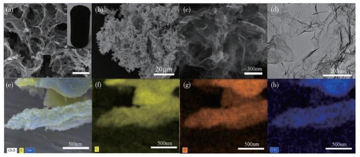
Fig. 1 shows the FESEM images of the as-prepared RGOA and RGOA/δ -MnO2- 160 mg samples. As can be seen in Fig. 1a, the RGOA shows a 3D porous frame-work structure that not only facilitates the catalytic reactions but also becomes an interfacial reactive template for the growth of δ-MnO2[12]. In addition, it is also found that the RGOA/δ - MnO2 composite still maintained a honeycomb 3D porous network structure (Fig. 1b). A few ultrathin δ-MnO2 NPs were observed on the RGOA surface from the SEM images with a higher magnification (Fig. 1c). In other words, these δ - MnO2 NPs were wrapped by the wrinkle graphene sheets. Fig. 1e presents the EDS mappings of the RGOA/δ - MnO2 sample. The elements of C, O, and Mn were distributed uniformly in the RGOA/δ - MnO2 (Fig. 1f, 1g, and 1h), implying that the δ-MnO2 sheets were successfully loaded into the graphene surface[13].
The N2 absorption- desorption measurements were applied to compare the specific surface areas of the samples, as shown in Fig. 2. The pristine RGOA sample exhibited a high BET specific area of ~140 m2·g-1, while a value of 149 m2·g-1 was observed in the RGOA/δ- MnO2 - 160 mg hybrid sample. It suggests that there was no obvious change in the surface area of RGOA even if loading enough δ-MnO2 NPs.
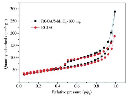
Fig. 3 indicates a typical low - magnification TEM image of RGOA/δ-MnO2-160 mg hybrid and its corresponding EDS spectrum. It is seen clearly that all the MnO2 NPs were wrapped by the wrinkle graphene sheets with a considerable dispersibility, while the signal of Mn element is identified in the EDS spectrum, confirming the existence of MnO2 in the hybrid again. It is worth noting that the signal of Cu is from the copper grids, while the K peak might be associated with the use of KMnO4 during the synthesis process.
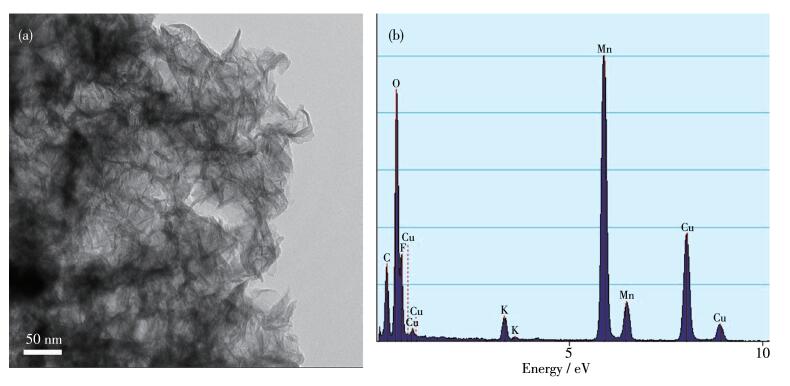
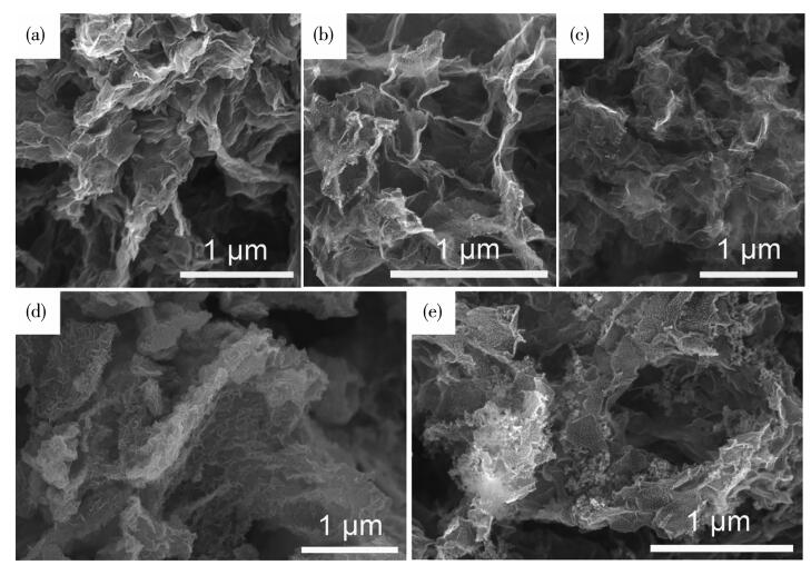
Fig. 4 compares the FESEM images of RGOA/δ - MnO2 hybrids with various MnO2 contents. As can be seen, when the MnO2 content was less than 160 mg, the hybrid displays a characteristic of wrinkle 3D graphene framework. The MnO2 NPs cann′t be distinguished due to their small sizes and good insertion into RGOA. That is to say, most of MnO2 NPs were wrapped by the wrinkle graphene nanosheets in this case. Nevertheless, when the MnO2 content exceeded 160 mg, a serve aggregation of NPs occurred, leading to the direct exposure of MnO2 particles in the air or electrolyte. The 3D network feature of RGOA disappeared due to an influence from the excessive MnO2. In other words, the MnO2 particles cann′t form a good contact with the conductive graphene in this case.
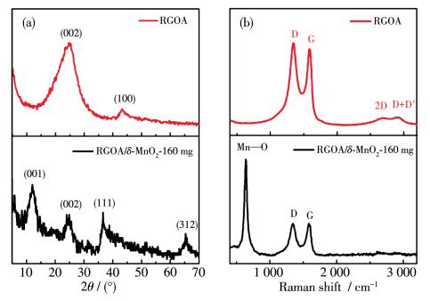
The phase structure of RGOA and RGOA/δ-MnO2- 160 mg samples were investigated by both the XRD patterns and Raman spectra. Fig. 5a displays that all the diffraction peaks of RGOA/δ-MnO2 -160 mg can be assigned to the phases of graphene and tetragonal δ - MnO2 (PDF No. 42 - 1316) [12]. Fig. 5b shows that the RGOA owns two sharp peaks at 1 348 and 1 587 cm-1, which correspond to the D and G bands of graphene, respectively. Moreover, two weak peaks around 2 650 and 2 900 cm-1 are assigned to G′ and D+D′ of graphene, implying that there might be a few defects in the RGOA. For the RGOA/δ - MnO2 - 160 mg sample, a sharp peak appears at 633 cm-1 in addition to the D and G peaks from the graphene, and this additional peak can be attributed to the tensile vibration of Mn—O lattice, indicating the existence of crystallized δ - MnO2 NPs again[14].
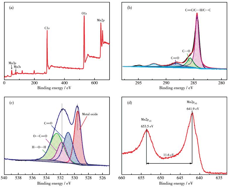
To further investigate the chemical composition and surface electronic state of the RGOA/δ-MnO2 - 160 mg hybrid sample, the XPS were performed, and the results were shown in Fig. 6. By a careful inspection of wide region spectroscopy and elemental analysis, the characteristic signals attributed to C1s, O1s, and Mn2p can be observed clearly (Fig. 6a), indicating the coexistence of C, O and Mn components. It is worth noting that the carbon signal (C1s, 284.9 eV) originates from RGOA (Fig. 6b), the peak at 529.8 eV (Fig. 6c) is associated with the O1s signal in anhydrous (Mn—O—Mn) and hydrated (Mn—O—H) manganese oxides, respectively. In the Mn2p spectrum displayed in Fig. 6d, two peaks located at 641.9 and 653.5 eV correspond to the binding energies of Mn2p3/2 and Mn2p1/2, in good accordance with a previous report[15].
A series of electrochemical tests were also conducted to study the Li - ion storage properties of a LIB anode in the half lithium-ion cell. Fig. 7a shows the CV plots of a RGOA/δ-MnO2 -160 mg anode at a scan rate of 0.1 mV·s-1 for the first three cycles. During the nega-tive scan process of the first cycle, a sharp cathodic peak appeared at 0.1 V, corresponding to the intercalation/deintercalation processes of Li ions. Meanwhile, there was also a broad peak at ~0.7 V, implying the formation of a SEI layer on the surface of anode. In total, the above electrochemical processes can be described as the following reactions[16-18]:
|
|
(2) |
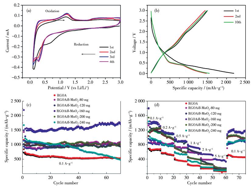
From the second cycle, the cathodic peak at 0.1 V turned to 0.3 V, suggesting an irreversible structural or textural changes due to the formation of Li2O and metallic manganese[19]. The disappearance of the cathodic around 0.7 V implies that the formation of SEI layer has been accomplished during the second cycle. Similarly, during the positive scan process of the first cycle, there were two anodic peaks at 1.3 and 2.1 V, corresponding to the oxidation of Mn0 to Mn2+ and Mn4+, respectively. The CV curves can be overlapped well after the second cycle, implying that this RGOA/δ - MnO2 anode owns an excellent structural stability and electrochemical reversibility.
Fig. 7b also shows the discharge - charge voltage profiles of a RGOA/δ - MnO2 - 160 mg anode, which delivered an initial discharge and charge (or reversible) capacity of 2 192.2 and 1 493.8 mAh·g-1, respectively. It determines an initial Columbic efficiency of 68.1% at 0.1 A·g-1. Such an initial capacity loss might be caused by the formation of SEI layer. This process refers to both the electrolyte decomposition and the reaction of the oxygen containing functional groups on 3D RGOA/δ-MnO2 with lithium ions. Despite the initial capacity loss, the well - overlapped charge/discharge profiles after the second cycle demonstrates an excellent reversibility of the 3D RGOA/δ-MnO2 anode. Additionally, a large voltage plateau located at ~0.50 V was observed in the first three cycles, being consistent with the reduction (or cathodic) peaks of voltages described in the CV profiles.
In order to find a suitable loading amount of δ - MnO2, the GCD profiles of the RGOA/δ - MnO2 electrodes with various compositions are displayed in Fig. 7c. These electrodes were measured at a current density of 0.1 A·g-1 and undergone 70 charge/discharge cycles. The result shows that the specific capacity of RGOA/δ - MnO2 increased firstly and then decreased with rising the δ - MnO2 loading amount, reaching a maximum value of 1 701.9 mAh·g-1 after 70 cycles at a δ-MnO2 amount of 160 mg. Compared to the single RGOA electrode, the enhanced specific capacity can be attributed to a high theoretical capacity of MnO2 (1 230 mAh·g-1). In contrast, the specific capacity of RGOA was just 538 mAh·g-1. It′s worth noticing that the specific capacity of RGOA/δ-MnO2-160 mg is much higher than the theoretical capacity of MnO2, which is a result of the enhanced conductivity and the suppressed volume expansion after using a 3D porous framework RGOA matrix[12]. However, a further increase of δ - MnO2 content to 200 mg would also result in a decrease of the specific capacity, and the RGOA/δ-MnO2- 240 mg anode even displays a lower specific capacity than the single RGOA one[5]. The capacity of RGOA/δ-MnO2-160 mg increased and RGOA/δ-MnO2-240 mg decreased, whereas other materials are mostly stable with the cycle performances. This phenomenon might be associated with the environment or state of δ- MnO2 NPs. With increasing δ- MnO2 content, more and more δ - MnO2 NPs cann′t be wrapped completely by the graphene in RGOA, leading to a direct exposing of these particles to the electrolyte. As a result, the volume expansion and particle aggregation would be taken place, which will prevent forming a good electric contact of MnO2 with RGOA or the collector (Cu foil), leading to an unavoidable reduction of the conductivity. On the other hand, the exposed MnO2 particles will also result in a thickening of the SEI layer, which lengthens the transport distances of Li ions. In total, both the above two reasons are responsible for a poor battery performance after incorporating excessive δ-MnO2 NPs.
Fig. 7d displays the rate performance of the RGOA/δ-MnO2 anodes with varying the current density from 0.1 to 5 A·g-1 then to 0.1 A·g-1. For the RGOA/δ -MnO2 -160 mg, the reversible charge capacities were 1 426.5, 1 128.4, 897.1, 723.6, 534.6 and 386.2 mAh· g-1 at 0.1, 0.2, 0.5, 1, 2 and 5 A·g-1, respectively. Obviously, the lower the current density is, the more active sites the Li ions seize, which leads to higher specific capacity under lower current density. Herein, the current density reflects the charge/discharge rate. It means that the increase of charge rate would result in a reduction of specific capacity. When it recovered to 0.1 A·g-1, the RGOA/δ-MnO2-160 mg still maintained a high reversible capacity of 1 200.7 mAh·g-1 (~84% compared to initial capacity). In addition, the RGOA/δ-MnO2-160 mg anode also indicates much higher specific capacity than other ones at a current density of 5 A·g-1, implying that this material is more appropriate for working at a rapid charging/discharge condition. It also suggests that a suitable ratio of δ-MnO2 to RGOA is crucial to achieve both the good rate performance and cyclic stability. The ideal case is that the δ -MnO2 NPs should be distributed on the surface of RGOA dispersively.
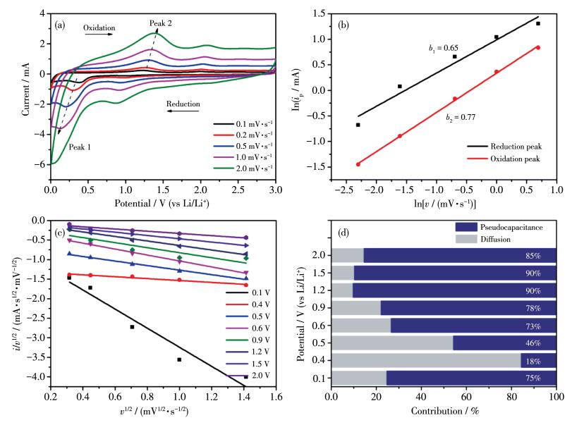
It is speculated that the excellent rate performance of RGOA/δ- MnO2-160 mg might be related with a pseudocapacitive contribution. Accordingly, the CV curves at incremental scan rates (0.1 to 2 mV·s-1) are shown in Fig. 8a. The similar shapes of the CV curves at different scan rates, indicating that the RGOA/δ-MnO2 electrode has good reversibility. The capacitive effects of the total charge storage can be revealed according to the following equation[20]:
|
|
(3) |
For a better analysis, the equation can be reorganized as follows:
|
|
(4) |
Where ip represents the peak current density, v means the sweep rate, both a and b are adjustable parameters. Apparently, i obeys a power law relationship with v, while b can be obtained from the curve slope by plotting ln ip against ln v. When b approaches to 0.5, the system is dominated by a diffusion -controlled process; while b approaches to 1.0, the charge storage is mainly controlled by pseudocapacitance[21]. As is shown in Fig. 8b, the slope b values for peak 1 (cathodic peak) and peak 2 (anodic peak) were calculated to be 0.65 and 0.77, respectively. It means that the capacitance contribution cann′t be neglected for a RGOA/δ-MnO2 - 160 mg electrode.
Furthermore, the pseudocapacitive contribution can be quantified by another equation[22]:
|
|
(5) |
For better fitting, this equation can be rewritten by:
|
|
(6) |
Where i represents the measured current density, k1 and k2 are the adjustable parameters. Herein, k1 represents the capacitance - controlled contribution while k2 stands for diffusion - controlled contribution. Typically, the linear profiles of i/v1/2 vs v1/2 are plotted in Fig. 8c. The values of k1 and k2 can be determined at various potentials (0.1 to 2.0 V) for determining the diffusion coefficient of Li+ ions in the electrodes. Accordingly, the normalized results are displayed in Fig. 8d. It is observed clearly that the electrochemical reactions occurred at the potentials except 0.4 and 0.5 V are dominated by a capacitance -controlled process. Dominant pseudocapacitive contribution means more Li ions involved in surface reactions during electrochemical process. At 0.4 or 0.5 V, the battery displays a poor capacitive contribution (18% and 46%, respectively), which might be related to the lithiation/delithiation reactions occurred in this potential range. As is mentioned previously in Fig. 7b, a large voltage plateau appeared a ~0.50 V in the discharge profile of a battery, corresponding to the insertion process of Li ions.
Furthermore, we also compare the RGOA/δ-MnO2- 160 mg with other reports (Table 1). It is found clearly that a charge/discharge rate of 0.1 A·g-1 is the most commonly used for characterizing the actual specific capacity of a LIB anode. Besides, nearly all the LIBs containing transitional metal oxide anodes display high discharge and reversible capacities during the first cycle. Then, a sharp decrease of specific capacity usually exhibited between first and second discharge process, which can be ascribed to large amount of SEI formation caused by defects in graphene and irreversible conversion upon lithiation. Therefore, it is not reliable to compare the first specific discharge/charge capacity of a LIB device. We always make a comparison of the actual LIB performance after 70~100 cycles. As shown in Table 1, it is worth mentioning that the RGOA anodes referred in this work display both excellent rate performance and longterm stability.
 下载:
导出CSV
下载:
导出CSV
| Anode | Specific capacity/(mAh·g-1) | Cycle number | Current density/(A·g-1) | Ref. |
| RGOA/δ-MnO2-160 mg | 1 701.9 | 70 | 0.1 | This work |
| 3D porous carbon nanosheets/SiO2 | 635.2 | 120 | 0.1 | [23] |
| 3D RGOA/ultrafine SnO2 | 778 | 100 | 0.1 | [24] |
| 3D RGOA/porous hollow SnO2 | 620 | 200 | 0.05 | [25] |
| 3D N-doped RGOA/CuO | 725.3 | 100 | 0.1 | [26] |
| 3D RGOA/ultrafine Fe3O4 | 2 136 | 100 | 0.5 | [27] |
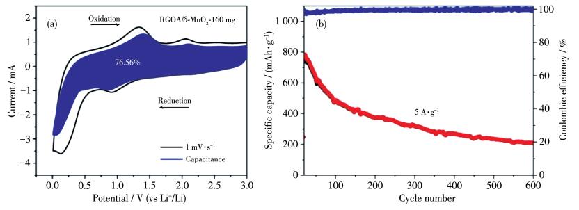
Furthermore, the normalized contribution from the pseudocapacitance-controlled process is also displayed in Fig. 9a. In other words, the calculation result will rep-resent an average value from the contribution of differ-ent potentials. After an integral calculation, the LIB device made with the RGOA/δ-MnO2-160 mg electrode delivered a pseudocapacitive contribution of ~76.56% to whole current at a moderate scan rate of 1 mV·s-1. The main charge-discharge mechanism is thus a pseudocapacitive behavior, which is an ultrafast charge storage process and contributes to the high rate performance. Additionally, the long-term cyclic stability and high charge/discharge performance of RGOA/δ - MnO2- 160 mg electrode were also examined and the results were indicated in Fig. 9b. As can be seen, the measurements were conducted at a high current density of 5 A· g-1 for 600 cycles. After undergoing 600 discharge/charge cycles, a large reversible charge capacity of 241.1 mAh·g-1 remained in the Li - ion battery, implying the RGOA/δ - MnO2 electrode displays an excellent recycling stability.
In summary, the RGOA/δ- MnO2 composites with an interconnected 3D structure were fabricated hydrohermally by in situ loading ultrathin δ - MnO2 NPs in RGOA, while KMnO4 was used as the raw for synthesizing δ-MnO2 NPs. The influence of KMnO4 adding amounts (namely, the MnO2 contents) was investigated on both the morphology and electrochemical performance of the RGOA/δ-MnO2 composite products. After optimizing the composite compositions, the RGOA/δ - MnO2 - 160 mg anode displayed the most excellent reversible specific capacity of 1 701.9 mAh·g-1 even after 70 cycles at a charge/discharge rate of 0.1 A·g-1 and delivered reversible capacity as high as 210.5 mAh·g-1 even after 600 cycles at 5 A·g-1. The excellent performance of RGOA/δ-MnO2 -160 mg is attributed to the synergistic effect of pseudo-capacitance contribution (~76.56% at 1 mV·s-1), small size of δ-MnO2 and porous network structure of RGOA after a deep and comprehensive analysis.
Tan Y B, Jia Z Q, Sun J Y, Wang Y Z, Cui Z H, Guo X X. J. Mater. Chem. A, 2017, 5(46): 24139-24144 doi: 10.1039/C7TA08236C
Li Z F, Wu S J, Ding H, Lu H M, Liu J Y, Huo Q S, Guan J Q, Kan Q B. New J. Chem. , 2013, 37: 4220-4229 doi: 10.1039/c3nj00982c
Pumera M. Energy Environ. Sci. , 2011, 4(3): 668-674 doi: 10.1039/C0EE00295J
Chen W F, Li S R, Chen C H, Yan L F. Adv. Mater. , 2011, 23: 5679-5683 doi: 10.1002/adma.201102838
Hou Y, Cheng Y W, Hobson T, Liu J. Nano Lett. , 2010, 10: 2727-2733 doi: 10.1021/nl101723g
Ji C C, Xu M W, Bao S J, Lu Z J, Cai C J, Chai H, Wang R Y, Yang F, Wei H. New J. Chem. , 2013, 37(12): 4199-4205 doi: 10.1039/c3nj00599b
Liao J Y, Higgins D, Lui G, Chabot V, Xiao X, Chen Z. Nano Lett. , 2013, 13(11): 5467-5473 doi: 10.1021/nl4030159
Mahmoudian M R, Alias Y, Basirun W J, Woi P M, Sookhakian M. Sens. Actuators B, 2014, 201: 526-534 doi: 10.1016/j.snb.2014.05.030
Zhu S, Zhang H, Chen P, Nie L H, Li C H, Li S K. J. Mater. Chem. A, 2015, 3: 1540-1548 doi: 10.1039/C4TA04921G
Liu J T, Ge X, Ye X X, Wang G Z, Zhang H M, Zhou H J, Zhang Y X, Zhao H J. J. Mater. Chem. A, 2016, 4: 1970-1979 doi: 10.1039/C5TA08106H
Xia H, Lai M O, Lu L. J. Mater. Chem. , 2010, 20(33): 6896-6902 doi: 10.1039/c0jm00759e
Liu S Y, Zhu Y G, Xie J, Huo Y, Hui Y Y, Zhu T J, Cao G S, Zhao X B, Zhang S C. Adv. Energy. Mater. , 2014, 4: 1301960 doi: 10.1002/aenm.201301960
Hu X, Chen J X, Zeng G, Jia J C, Cai P W, Chai G L, Wen Z H. J. Mater. Chem. A, 2017, 5(45): 23460-23470 doi: 10.1039/C7TA08169C
Song C, Guo B B, Sun X F, Wang S G, Li Y T. Chem. Eng. J. , 2019, 358: 1139-1146 doi: 10.1016/j.cej.2018.10.119
Trahey L, Karan N K, Chan M K Y, Lu J, Ren Y, Greeley J, Balasubramanian M, Burrell A K, Curtiss L A, Thackeray M M. Adv. Energy Mater. , 2013, 3: 75 doi: 10.1002/aenm.201200037
Zhao B, Lu M N, Wang Z X, Jiao Z, Hu P F, Gao Q, Jiang Y, Cheng L L. J. Alloys Compd. , 2016, 663: 180-186 doi: 10.1016/j.jallcom.2015.12.018
Chen C, Wu M Q, Wang S Z, Yang J, Qin J G, Peng Z, Feng T T, Gong F. RSC Adv. , 2017, 7(61): 38639-38646 doi: 10.1039/C7RA06871A
Reddy A L M, Shaijumon M M, Gowda S R, Ajayan P M. Nano Lett. , 2009, 9(3): 1002-1006 doi: 10.1021/nl803081j
Wang J Y, Deng Q L, Li M J, Jiang K, Hu Z G, Chu J H. Nanoscale, 2018, 10(6): 2944-2954 doi: 10.1039/C7NR08191J
Augustyn V, Come J, Lowe M A, Kim J W, Taberna P L, Tolbert S H, Abruna H D, Simon P, Dunn B. Nat. Mater. , 2013, 12(6): 518-522 doi: 10.1038/nmat3601
Chen X D, Lv L P, Sun W W, Hu Y Y, Tao X C, Wang Y. J. Mater. Chem. A, 2018, 6(28): 13705-13716 doi: 10.1039/C8TA03176B
Lesel B K, Ko J S, Dunn B, Tolbert S H. ACS Nano, 2016, 10(8): 7572-7581 doi: 10.1021/acsnano.6b02608
Mao J X, Chen M M, Deng Y C, Liu H, Ju Z C, Xing Z, Cao X C. J. Mater. Sci. , 2019, 54(19): 12767-12781 doi: 10.1007/s10853-019-03812-1
Song D Y, Wang S S, Liu R Z, Jiang J L, Jiang Y, Huang S S, Li W R, Chen Z W, Zhao B. Appl. Surf. Sci. , 2019, 478: 290-298 doi: 10.1016/j.apsusc.2019.01.143
Choi J, Myung Y, Gu M G, Kim S K. J. Ind. Eng. Chem. , 2019, 71: 345-350 doi: 10.1016/j.jiec.2018.11.045
Feng C N, Dong L, Meng J K, Zheng X C, Zheng G P. J. Alloys Compd. , 2019, 784: 915-922 doi: 10.1016/j.jallcom.2019.01.119
Kopuklu B B, Tasdemir A, Gursel S A, Yurum A. Carbon, 2021, 174: 158-172 doi: 10.1016/j.carbon.2020.12.049

Figure 1 FESEM images of (a) RGOA (inset: photograph of RGOA) and (b, c) RGOA/δ-MnO2-160 mg and (d) TEM image of RGOA/δ-MnO2-160 mg; EDS mappings of RGOA/δ-MnO2-160 mg: (e) survey image, (f) C, (g) O, and (h) Mn

Figure 2 Typical N2 adsorption-desorption isotherms of as-grown RGOA and RGOA/δ-MnO2-160 mg samples

Figure 3 (a) TEM image and (b) corresponding EDS spectrum of RGOA/δ-MnO2-160 mg hybrid

Figure 4 FESEM images of RGOA/δ-MnO2 with different adding amounts: (a) 80 mg, (b) 120 mg, (c) 160 mg, (d) 200 mg and (e) 240 mg

Figure 5 (a) XRD patterns and (b) Raman spectra of as-prepared RGOA and RGOA/δ-MnO2-160 mg

Figure 6 XPS spectra of RGOA/δ-MnO2-160 mg: (a) full spectrum; (b) C1s; (c) O1s; (d) Mn2p

Figure 7 (a) CV and (b) GCD plots of RGOA/δ-MnO2-160 mg anode; (c) Cycling performance profiles of RGOA/δ-MnO2 anodes at a current density of 0.1 A·g-1; (d) Rate performance of RGOA/δ-MnO2 anodes

Figure 8 Electrochemical kinetics analysis of RGOA/δ-MnO2-160 mg: (a) CV curves at different scan rates from 0.1 to 2.0 mV·s-1; (b) relationships between ln ip and ln v; (c) plots of i/v1/2 vs v1/2 and (d) normalized contribution ratios of pseudocapacitive (blue) and diffusion-controlled (gray) capacities at various potentials

Figure 9 (a) CV curve with the pseudocapacitive contribution shown by the shaded area at a scan rate of 1 mV·s-1; (b) Long-term cycling performance and Columbic efficiencies of RGOA/δ-MnO2-160 mg anode at 5 A·g-1 (Note that the profiles in (b) is initialized at the 75th cycle for avoiding the large fluctuation during these cycles)
Table 1. Comparison on the actual Li+ storage performance of 3D graphene anodes
| Anode | Specific capacity/(mAh·g-1) | Cycle number | Current density/(A·g-1) | Ref. |
| RGOA/δ-MnO2-160 mg | 1 701.9 | 70 | 0.1 | This work |
| 3D porous carbon nanosheets/SiO2 | 635.2 | 120 | 0.1 | [23] |
| 3D RGOA/ultrafine SnO2 | 778 | 100 | 0.1 | [24] |
| 3D RGOA/porous hollow SnO2 | 620 | 200 | 0.05 | [25] |
| 3D N-doped RGOA/CuO | 725.3 | 100 | 0.1 | [26] |
| 3D RGOA/ultrafine Fe3O4 | 2 136 | 100 | 0.5 | [27] |
 下载: 导出CSV

 扫一扫看文章

扫一扫关注我们
