Citation:
Kang Liang, Daxiong Wu, Yurong Ren, Xiaobing Huang, Jianmin Ma. Research progress on Na3V2(PO4)2F3-based cathode materials for sodium-ion batteries[J]. Chinese Chemical Letters,
2023, 34(6): 107978.
doi:
10.1016/j.cclet.2022.107978
Research progress on Na3V2(PO4)2F3-based cathode materials for sodium-ion batteries
English
Research progress on Na3V2(PO4)2F3-based cathode materials for sodium-ion batteries
School of Materials Science and Engineering, Jiangsu Province Engineering Research Center of Intelligent Manufacturing Technology for the New Energy Vehicle Power Battery, Changzhou University, Changzhou 213164, China
b.
School of Physics and Electronics, Hunan University, Changsha 410082, China
c.
College of Chemistry and Materials Engineering, Hunan University of Arts and Science, Changde 415000, China
d.
School of Chemistry, Tiangong University, Tianjin 300387, China
Received Date:
05 August 2022 Accepted Date:
01 November 2022 Revised Date:
31 October 2022 Available Online:
15 June 2023
Abstract:
Sodium-ion batteries (SIBs) have received significant attention in large-scale energy storage due to their low cost and abundant resources. To obtain high-performance SIBs, many intensive studies about electrode materials have been carried out, especially the cathode material. As various types of cathode material for SIBs, a 3D open framework structural Na3V2(PO4)2F3 (NVPF) with Na superionic conductor (NASICON) structure is a promising cathode material owing to its high operating potential and high energy density. However, its electrochemical properties are severely limited by the poor electronic conductivity due to the insulated [PO4] tetrahedral unit. In this review, the challenges and strategies for NVPF are presented, and the synthetic strategy for NVPF is also analyzed in detail. Furthermore, recent developments of modification research to enhance their electrochemical performance are discussed, including designing the crystal structure, adjusting the electrode structure, and optimizing the electrolyte components. Finally, further research and application for future development of NVPF are prospected.
Energy problems and environmental crises are critical issues concerning our civilization. Lithium-ion batteries (LIBs) have been widely applied in portable electronic devices due to their high energy density, long cycle life, and wide operating window [1,2]. However, the low abundance and uneven distribution of Li resources in the Earth's crust would limit its applications [3–6]. Thus, a new energy storage system should be developed to meet the growing demands for large-scale energy storage. Sodium, the fourth most abundant element in the Earth's crust, can effectively alleviate the shortage of lithium resources [7]. The main characteristics between lithium and sodium are presented in Table S1 (Supporting information). Recently, sodium-ion batteries (SIBs) have captured much attention due to their low cost and abundant sodium resources [8]. In contrast to LIBs, the SIBs with similar "rocking chair" working principles are more advantageous in large-scale energy storage [9,10]. In addition, Al foil can be used in SIBs as the current collector for the anode and cathode because Al does not alloy with Na, which can significantly reduce the cost of the whole battery [11]. However, the large radius of Na (1.02 Å for Na+vs. 0.76 Å for Li+) results in the sluggish diffusion kinetics of Na+ [12]. Thus, finding a suitable electrode is a high challenge for SIBs.
As the most important component for SIBs, the cathode influences energy density and cyclic performance [13,14]. As a result, it is critical to develop a high-performance cathode material for SIBs. Tables S2 and S3 (Supporting information) summarize the typical cathode materials and their electrochemical properties, such as transition metal oxides (e.g., Na0.44MnO2 [15], Na0.92Li0.40Ni0.73Co0.12O2 [16], Na2/3Ni1/3Mn2/3O2 [17]), polyanionic compounds (e.g., NaFePO4 [18], Na3V2(PO4)3 [19,20], Na3V2(PO4)2F3 [21,22]), and Prussian blue analogues (e.g., Na2Fe[Fe(CN)6] [23], NaxCo[Fe(CN)6)y [24]). Among these, fluorine-rich phase sodium vanadium fluorophosphate (Na3V2(PO4)2F3, NVPF) with Na superionic conductor (NASICON) structure has been regarded as a promising cathode material for SIBs due to high operating voltage (~3.95 V) and high theoretical energy density (507 Wh/kg) [25–27]. However, the poor electrochemical performance of NVPF seriously limits its further application due to its low intrinsic electronic conductivity. Thus, appropriate strategies should be applied to enhance the electronic conductivity and Na+ diffusion kinetics for NVPF, thereby greatly improving the electrochemical performance of SIBs.
In the recent research, the strategies to improve electrochemical performance include (1) designing the crystal structure, which can shrink the bandgap, resulting in higher intrinsic conductivity, and changing the barrier of Na+ during the charge and discharge process, enhancing the diffusion kinetics; (2) adjusting the electrode structure to build multi-level structure, which could accelerate the ion and electron's diffusion. Besides, it also can build electron transport with higher conductivity, enhancing electrochemical performance; (3) optimizing the electrolyte components, improving the stability of the material in the cycling process, and further enhancing the electrochemical performance of the battery in a wide temperature range. In this review, we focus on those challenges of NVPF on the large-scale application for SIBs and the latest progress to deal with them. In part 2, the crystal structure and property of NVPF are briefly introduced. In part 3, the synthetic methods for NVPF are summarized. In part 4, the recent breakthroughs in dealing with challenges for NVPF are introduced. In part 5, the summary and future outlooks for NVPF are also proposed.
2.
Crystal structure and property of NVPF
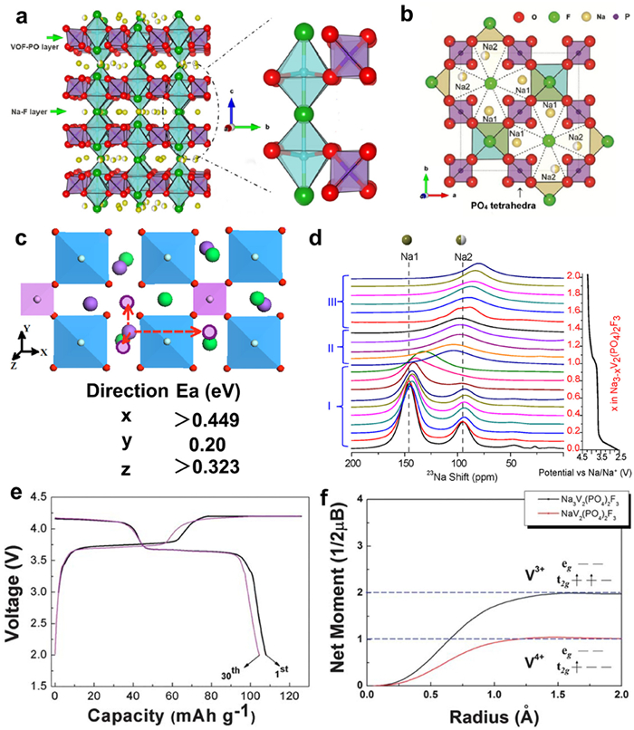
The Na3M2(PO4)2F3 (M = Al3+, V3+, Cr3+, Fe3+, Ga3+) compounds were first synthesized by hydrothermal or solid-state method and analyzed the crystal structure as early as 1999. As a result, the NVPF crystal structure belongs to the tetragonal system with a space group of P42/mnm, and the unit cell parameters are as follows: a = b = 9.047(2) Å, c = 10.705(2) Å and V = 876.2(3) Å3 [28], showing an open 3D framework alternate composing a [V2O8F3] bi-octahedral unit and [PO4] tetrahedral unit, forming the channel induced along with the [110] and [110] axis for fast Na+ migration, as shown in Figs. 1a and b [29]. Besides, the first principles calculation was performed based on the density functional theory (DFT) method further to confirm the migration pathway of Na+ [30]. As shown in Fig. 1c, three migration pathways along the x, y, and z directions were selected to calculate the migration activation energy (Ea). According to the Ea value, the path along the y-direction (the channel of Na+ composed of two [V2O8F3] bi-octahedral and [PO4] tetrahedra) presented the lowest Ea value of 0.2 eV, showing a possible migration way of Na+ in NVPF crystal. The [PO4] unit can provide a stable framework structure for Na+ migration. However, the electron transmission is obstructed by the insulating [PO4] unit, which will affect the migration of electrons in the crystal. Therefore, the hindered electron transfer path results in low intrinsic electronic conductivity (~10−12 S/cm), thereby greatly restricting its electrochemical performance.
Figure 1
Figure 1.
Fig. 1. (a, b) Structural characterization of NVPF. Reproduced with permission [29]. Copyright 2018, Elsevier. (c) Coordination polyhedral around the Na site and possible examples for a long-range ion migration path along the x, y, and z directions. Reproduced with permission [30]. Copyright 2014, American Chemical Society. (d) Ex situ23Na NMR spectra of NVPF electrodes at different states of charge. Reproduced with permission [31]. Copyright 2014, American Chemical Society. (e) Charge and discharge profile of NVPF. (f) Integrated spin as a function of integration radius around vanadium ions for NaxVPF at x = 3 and x = 1. Reproduced with permission [32]. Copyright 2012, Royal Society of Chemistry.
In addition, two types of Na sites with an occupied ratio of 2:1 were further investigated by the 23Na NMR technique (Fig. 1d), and the fully occupied Na site and partially occupied Na site was named Na (1) and Na (2), respectively [31]. Shakoor et al. [32] firstly proved the Na storage property combined with the first principles calculation and experiment. The charge and discharge curves of NVPF are shown in Fig. 1e. Two redox potentials located at 3.6 and 4.2 V vs. Na+/Na are associated with the redox reaction of V3+/V4+, corresponding to the two-phase structural evolution. The net spin moment further confirmed that the electrochemical activity of NaxV2(PO4)2F3 (1 ≤ x ≤ 3) is attributed to the redox reaction of V3+/V4+ (Fig. 1f). Thus, the structural evolution and sodium insertion/desertion process of NVPF can be described by following Eqs. 1 and 2 [33]:
(1)
(2)
As a result, a high theoretical capacity of 128 mAh/g and a theoretical energy density of 507 Wh/kg are obtained.
3.
Synthetic strategies for NVPF
Up to now, the synthetic strategies of NVPF have mainly focused on the traditional solid-state, sol-gel, and solvothermal/hydrothermal methods (Table S4 in Supporting information). In the following part, some works are introduced and described separately to discuss how to improve the electrochemical performance of NVPF from synthetic strategies.
3.1
Solid-state method
The solid-stated method is a common strategy for synthesizing the NVPF material. This method has the advantages of a simple process and relatively low cost to prepare the electrode material [34]. To promote the purity of the product and shrink the reaction time, nanosized raw materials and higher calcining temperatures could be used. Our group and co-authors reported a solid-stated method to prepare NVPF/C nanoparticles using NH4VO3, NH4H2PO4, and NaF as raw materials and pitch as a carbon source (Fig. S1a in Supporting information) [35]. Observed by the SEM images (Figs. S1b and c in Supporting information), the NVPF/C sample presents an agglomerated particle with small size. The morphology is similar to other samples synthesized by the solid-state method. However, this agglomeration structure will essentially limit the electrochemical performance due to the low diffusion kinetics of Na+. Thereafter, Ou et al. [36] used buckwheat and graphene as the carbon source to prepare the NVPF@C/G with 3D conductive network structure by solid-state method (Fig. S1d in Supporting information). As shown in the SEM image (Fig. S1e in Supporting information), the sample of NVPF@C/G delivers less agglomeration. This wrinkled graphene provides a connected channel for NVPF and further improves the electrochemical conductivity, resulting in a maximum specific capacity of 137.5 mAh/g at 0.2 C (Fig. S1f in Supporting information). Generally, the solid-state method synthesized the NVPF product has an irregular bulk without a specific morphology. Some recent studies have suggested that surfactants may play a role in the solid-stated approach to adjust morphology. For instance, Li et al. [37] used octadecyl amine as a surfactant to prepare the uniform NVPF/C nanocubes (NVPF-NC) via a solid-state method (Fig. S1g in Supporting information), which displays a high discharge capacity of 107.7 mAh/g at 30 C and excellent capacity retention of 97.8% after 200 cycles at a high rate of 10 C (Figs. S1h and i in Supporting information). Although the solid-state method is widely used in the synthesis of NVPF, there are some disadvantages to applying this method. For example, the particle size of the NVPF will increase during the calcinating process at high temperatures. Therefore, optimizing the solid-state strategy is still necessary to obtain NVPF with ideal particle size distribution.
3.2
Sol-gel method
The sol-gel method is another method to synthesize the NVPF. The raw materials were dissolved and mixed in the solution. The citric acid was added to the solution as the chelating agent to thoroughly mix different metal ions and a carbon source to realize the in-situ carbon coating [38]. Furthermore, the gas produced by the thermal decomposition of citric acid can play a role in pore formation, resulting in a porous structure. Lu et al. designed the 3D porous structural NVPF@N, S co-doped carbon (NVPF@NSC) by sol-gel method following freeze-drying technology (Fig. S2a in Supporting information) [39]. The obtained NVPF showed excellent structural stability and electrical conductivity due to its 3D framework structure (Figs. S2b and c in Supporting information), delivering remarkable cycle performance (92.1% capacity retention after 500 cycles at 5 C). In a recent work, the NVPF was synthesized utilizing the sol-gel method with NH4VO3, NH3H2PO4, NaF, citric acid, and graphene oxide (GO) as raw materials. This linked 3D carbonous architecture may result in a low specific surface area and favorable tap density [40]. Subramanian et al. also reported the NVPF-rGO by sol-gel method using the rGO as a fast electron-conducting network (Figs. S2d–f in Supporting information), delivering a large reversible capacity of 113 mAh/g and excellent cycle life (100% capacity retention after 10,000 cycles at 30 C) [41]. However, the sol-gel method suffers from the same limitations as the solid-state method: The generated samples lack uniform shape and tend to agglomerate, restricting their use.
3.3
Solvothermal/hydrothermal methods
Although both the solid-state and sol-gel methods have been widely used in synthesizing NVPF composites, the morphologies and size of NVPF are challenging to control. To get the unique structure for the high performance of NVPF, the solvothermal/hydrothermal method has been used. Compared with the normal method in ambient temperature and pressure, this method could increase the reaction rate to obtain the specific structure. For example, Cai et al. [42] developed a hydrothermal method to synthesize NVPF microcubes (~2 µm) encapsulated by a cross-linked 3D graphene network (NVPF@rGO) (Figs. S3a–c in Supporting information), delivering a high reversible capacity of 119 mAh/g at 0.5 C and excellent capacity retention of 98% after 2000 cycles at 20 C. Moreover, Zhu et al. [43] also used graphene oxide as the conductive network to fabricate the nanoparticulate NVPF (NVPF⊂GN) (Fig. S3d in Supporting information). Notably, the NVPF nanoparticles (~50 nm) are distributed on GO nanosheets (Figs. S3e and f in Supporting information). Compared with the sample without adding GO, this structure has a larger specific surface area, stronger conductivity, and more active sites, leading to improved electrochemical performance. In addition, this solvothermal/hydrothermal method is a common strategy to control the morphology of the NVPF. In the liquid system, solvent, content, surfactant species, and pH value play a significant role in morphology control [44,45]. Our group reported an NVPF microsphere with a porous structure by polyvinylpyrrolidone (PVP) assisted hydrothermal method (Fig. S3g in Supporting information) [46]. In this work, PVP was used as a soft template to form a PVP chain that facilitated the formation of the porous microsphere structure of NVPF. Compared with the bulk NVPF (Fig. S3h in Supporting information), the NVPF with porous micron spheres (Fig. S3i in Supporting information) exhibits a fast Na+ diffusion rate, resulting in high electrochemical performance with 127.8 mAh/g at 0.2 C (Fig. S3j in Supporting information). Solvothermal/hydrothermal method is a promising method to obtain purified and uniform material while it can realize the synthesis process that cannot be completed under conventional conditions. However, adjusting the parameters (e.g., the concentration of raw material, pH of solvent) in the hydrothermal process to achieve the controllable growth of crystal structure is the key to preparing NVPF by the hydrothermal/solvothermal method.
4.
Modification of NVPF
However, the inferior electrical conductivity of NVPF is a major issue resulting in narrow-scale application in energy storage. To solve this critical issue, many strategies have been investigated to improve the electrochemical performance of NVPF, such as designing the crystal structure, adjusting electrode structure, optimizing the electrolyte component. Table S5 (Supporting information) summarizes several representative modified strategies in recent and corresponding electrochemical properties.
4.1
Designing the crystal structure
4.1.1
Element doping
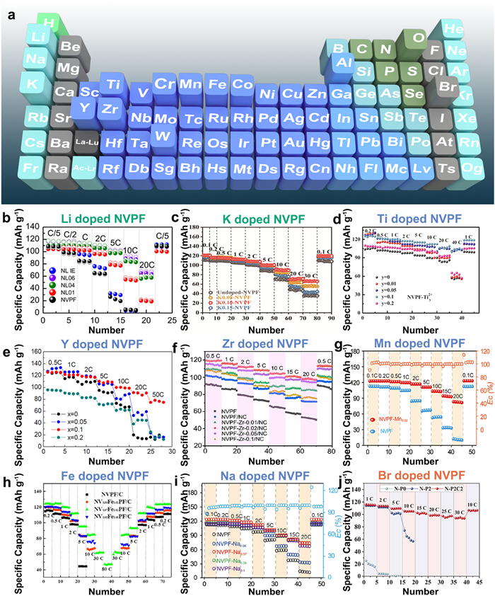
The insulating structure [PO4] results in significantly inferior conductivity, leading to poor rate capability of NVPF at a high-rate. Thus, utilizing an appropriate element doping could efficiently enhance the intrinsic transfer characteristics of NVPF [47]. Nowadays, many elements, for example, Li [48], K [49,50], Ti [51], Y [52], Cr [53], Zr [54], Co [55], Mn [56,57], Fe [58], Na [59], W [60], Al [61,62], Br [63], O [64,65], have been used as dopants in NVPF crystals (Fig. 2a).
Figure 2
Figure 2.
(a) The doping element on the Periodic Table of Elements. Rate performance of ion-doped NVPF: (b) Li+. Reproduced with permission [48]. Copyright 2018, Elsevier; (c) K+. Reproduced with permission [50]. Copyright 2021, Institute of Process Engineering, Chinese Academy of Sciences; (d) Ti2+. Reproduced with permission [51]. Copyright 2018, Elsevier; (e) Y3+. Reproduced with permission [52]. Copyright 2017, Royal Society of Chemistry; (f) Zr4+. Reproduced with permission [56]. Copyright 2021, Wiley-VCH; (g) Mn2+. Reproduced with permission [54]. Copyright 2021, Elsevier; (h) Fe2+. Reproduced with permission [58]. Copyright 2021, Elsevier; (i) Na+. Reproduced with permission [59]. Copyright 2021, Wiley-VCH; (j) Br−. Reproduced with permission [63]. Copyright 2022, Wiley-VCH.
Using elements doping with different ionic radius in Na sites can influence the lattice spacing, leading to different electrochemical performances. As the smallest metallic element, Li has been used to enhance the electrochemical performance of NVPF. Kosova et al. [48] adopted the Li to replace partial Na and synthesize the Na3-xLixV2(PO4)2F3 (x = 0, 0.1, 0.4 and 0.6) through a two-step solid-state method. They found that the V2O3 impurity was formed on the surface after the lower substitution of Li+. According to the electrochemical performance, this structure combined with conductive V2O3 and carbon coating network leads to higher performance than the original one (Fig. 2b). Besides, doping of K (1.38 Å) with a larger radius into the NVPF crystal can effectively expand the transmission channel of Na+ and stabilize the NASICON structure due to the internal stress during the charge and discharge process. According to the DFT result, the electronic and ionic conductivities of K-doped NVPF were improved, delivering a high capacity of 120.8 mAh/g at 0.1 C and an excellent rate capacity of 63 mAh/g at an ultra-high rate of 100 C (Fig. 2c) [50].
Partial replacement of V with suitable elements is significant due to the toxicity and expense of V. For instance, titanium (Ti) is generally considered a nontoxic and safe element, and Ti doping can effectively improve ionic and electronic conductivity. For example, Yi et al. [51] prepared a series of Ti-doped NVPF compounds with different valence states and different amounts of Ti. It was found that the VSU-doping (the valence state of the doping ion kept unchanged during the synthesis) and VSC-doping (the valence state changes during the synthesis) significantly influenced the morphology and electrochemical performance. Combined with the DFT calculation, the bandgap could be reduced after the Ti replaced the V site, improving electronic conductivity. The electrochemical performance of Ti0.12+ synthesized by the VSC-doping process showed 125 mAh/g at 0.2 C and high-rate capacity (i.e., 104 mAh/g at 40 C; 41 mAh/g at 200 C) (Fig. 2d). Besides, Liu et al. [52] prepared Na3V2-xYx(PO4)2F3/C composites using a citric acid-assisted sol-gel method. It was found that the intrinsic electrical conductivity and mobility of Na+ were significantly improved, showing the highest capacity of 121.3 mAh/g at 0.5 C and optimizing the performance of 80 mAh/g at 50 C (Fig. 2e). Guo et al. [54] reported the particle substitution of V in NVPF crystal by Zr (Na3V2-xZrx(PO4)2F3/NC, 0 ≤ x ≤ 0.1). It was found that the substitution of Zr into NVPF presented an effect on the sample size, showing a high reversible capacity of 119.2 mAh/g at 0.5 C and 98.1 mAh/g at 20 C (Fig. 2f).
Mn and Fe, the familiar magnetic element, have also gained wide attention as dopants in NVPF. For example, Zhang et al. [57] employed a tetraethylene glycol-assisted hydrothermal method followed by the CVD method to prepare the Na3V1.95Mn0.05(PO4)2F3@C hollow microspheres. It was found that substituting Mn2+ into NVPF could enlarge the crystal volume due to the larger radius of Mn2+ (0.97 Å) than V3+ (0.78 Å). When evaluated in SIBs as cathode, Na3V1.95Mn0.05(PO4)2F3@C composites delivered a high initial reversible capacity of 122.9 mAh/g at 0.2 C. Moreover, Gu et al. [56] also used Mn2+ to fabricate Mn2+-doped NVPF. They found that the electronic conductivity and Na+ transfer kinetics are improved by lattice regulation of aliovalent Mn2+ for V3+. Besides, the coexistence of V3+/V4+ was formed due to the charge balance theory by Mn2+ doping, resulting in fast kinetics of Na+. The results demonstrated that Na3V1.98Mn0.02(PO4)2F3 had the highest electronic conductivity and more rapid Na+ diffusion kinetics, resulting in the best reversible capacity and rate performance (i.e., 123.8 mAh/g at 0.1 C; 83.4 mAh/g at 20 C) (Fig. 2g). In addition, Li et al. [58] introduced a model based on Na3V2–2xFe2x(PO4)2F3 to investigate the optical concentration of Fe. It was found that the volcanic electronic conductivity and electron activation energy play an essential role in the high performance of NVPF. Hence, the optical NV0.97Fe0.03PF/C composites delivered the highest specific capacity of 126.7 mAh/g at 0.1 C and a maximum rate capacity of 47.1 mAh/g at an ultra-high rate of 80 C (Fig. 2h).
It is especially noteworthy that Gu et al. [59] used Na+ (1.02 Å) to replace particle V3+ (0.78 Å) and synthesize a series of Na3+2xV2-xNax(PO4)2F3 by aliovalent substitution. They found that the crystal defects were generated, and the mixed-valence states of V3+/V4+ were formed after Na+ substitution, thereby improving the electronic conductivity. Alternatively, the larger size of Na+ can enlarge the transmission channel of Na+, leading to higher Na+ diffusion kinetics. Moreover, the structural stability was also improved due to the stronger bond of Na−O than that of V−O. Finally, the Na-doped NVPF showed a high capacity of 123.6 mAh/g at 0.1 C and a good rate performance with a capacity of 77.5 mAh/g at 10 C (Fig. 2i).
Moreover, anion doping at the F sites in the NVPF crystal was also investigated to improve the sodium storage capability of NVPF. For example, the F atom could be replaced by an O atom to form a serial of Na3(VO1-xPO4)2F1+2x (0 ≤ x ≤ 1) [66–68]. For example, Li et al. [65] introduced the O element in the F sites of NVPF to prepare the Na3V2(PO4)2O1.6F1.4 compound, displaying a high capacity of 123.4 mAh/g at 0.5 C. After that, Hu et al. firstly selected another anion, Br−, to boost the electrochemical performance [63]. In this work, Br-doped NVPF@C spheres were fabricated by a one-step spray drying approach using polytetrafluoroethylene (PTFE) and cetyltrimethylammonium bromide (CTAB) as carbon source and bromine source, respectively. The DFT calculation revealed enhanced conductivity and a lower diffusion energy barrier after Br-doped. As a result, this structural Br-doped NVPF/C sphere displays a high discharge capacity of 116.1 mAh/g at 1 C and excellent rate performance with a capacity of 95.2 mAh/g at 30 C (Fig. 2j).
4.1.2
Specific crystal facet growing
Controlling the growth of crystal facets is also an effective way to increase the Na+ diffusion kinetics. On the one hand, the structure of the electrode material can be influenced by exposing certain specific crystal facets, which is conducive to improving the reaction kinetics at the interface [69,70]. On the other hand, by controlling the crystal growth direction, a more convenient pathway for ion transport can be provided [71,72]. For example, the Na[Li0.05Ni0.3Mn0.5Cu0.1Mg0.05]O2 with exposed {010} active facet [73] and (001) facet dominated Na2Ti3O7 [74] all present excellent electrochemical performance. Thus, using a reasonable method to induce selective growth of crystals, exposing high-performance crystal facets, can effectively improve the electrochemical performance of NVPF.
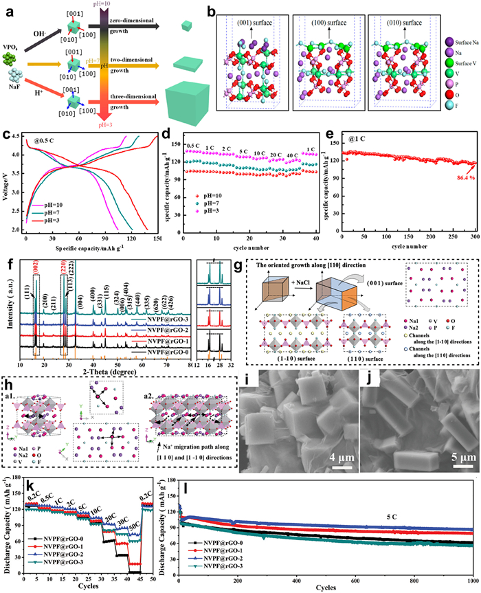
Li et al. [75] have reported a strategy to control crystal structure growth forward in a specific direction by adjusting the pH value (Figs. 3a and b). They found that surface energy and adsorption energy are essential in crystal growth. The surface energies of three facets were all enhanced in an acid environment as a consequence of the DFT calculation, allowing the raw material to be readily adsorbed on the crystal surface and improving the purity of NVPF. Combined with the Ketjenblack (KB) coating layer, the NVPF@KB at pH 3 delivers an ultrahigh initial specific capacity (138 mAh/g at 0.5 C), superior high-rate performance (122 mAh/g at 40 C), and stable cyclic performance (86.4% at 1 C after 300 cycles) (Figs. 3c–e). Besides, Zhu et al. [76] also introduced NaX (X = F, Cl, Br) as a crystal surface inducer via a hydrothermal method to induce the crystal facet to grow dominantly along with the [110] crystal axis, thereby exposing more sodium-rich (001) crystal facet to obtain higher electrochemical performance, as shown in Fig. 3f. In this work, the author found that the (220) peak will increase after adding the NaCl, which means that the NVPF crystal will grow along the [110] axis, exposing more (001) crystal facets with more Na+ and providing more active "gates" for Na+ diffusion (Figs. 3g and h). From the changed in morphologies (Figs. 3i and j), this structure has changed significantly from a cube to a cuboid, demonstrating that controlling the growth of crystal facets along a specific direction could optimize the material structure. As a result, a high discharge capacity of 127.5 mAh/g was obtained at 0.2 C. Even at a high rate of 50 C, the discharge capacity of 73.7 mAh/g remained (Fig. 3k). After 1000 cycles at 5 C, the capacity retention of obtained NVPF@rGO-2 was still 83.21% (Fig. 3l).
Figure 3
Figure 3.
(a) Schematic diagram of the growth of the NVPF samples. (b) Calculated structures (side view) of (001), (100), and (010) surfaces of the NVPF crystal. Electrochemical performance of NVPF@KB at different pH values: (c) Charge and discharge curves, (d) Rate capacity. (e) Cycle performance of NVPF@KB at pH 3. Reproduced with permission [75]. Copyright 2019, American Chemical Society. (f) XRD patterns and enlarged XRD patterns. (g) The schematic diagram shows the correlation between the change in diffraction peaks and the crystal evolution of NVPF and the corresponding atomic structures of the (001), (110), and (110) facets (e). (h) Schematic diagram showing the difference in Na+ migration in the original NVPF (a1) and NVPF grown along with the (110) axis (a2). SEM images of NVPF (i) and NVPF adding NaCl (j). Rate capacity (k) and cycle performance (l) for NVPF@rGO. Reproduced with permission [76]. Copyright 2020, Royal Society of Chemistry.
The construction of the second particle by a multi-level structure can enhance the diffusion rate of ion and electron. Besides, building transport channels with high electronic conductivity has the most significant impact on improving the performance of NVPF.
4.2.1
Nanosizing and hierarchical structure designing
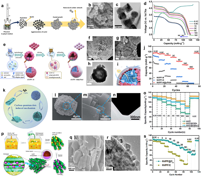
The morphologies and size of the NVPF present essential factors to influence the electrochemical performance [77]. Controlling the size to nanoscale can shorten the diffusion lengths of Na+ and increase the contact area between electrode and electrolyte, thus improving ion transport efficiency [78]. Park et al. [79] reported a polyol refluxing method in diethylene glycol to synthesize the nanostructured NVPF/C (Fig. 4a). During this polyol refluxing process, the nuclei gradually agglomerate to grow the crystals and eventually generate NVPF nanoparticles with a carbon network (Figs. 4b and c), leading to a high discharge capacity (e.g., 118 mAh/g at 1 C) and excellent rate performance (e.g., 105.9 mAh/g at 50 C) (Fig. 4d).
Figure 4
Figure 4.
(a) Schematic illustration of polyol-based NVPF/C synthesizing protocol. SEM (b) and TEM images (c) of NVPF/C nanoparticles. (d) Charge and discharge curves of NVPF/C. Reproduced with permission [79]. Copyright 2019, Springer Nature. (e) Schematic of the preparation of NVPF-H@cPAN. SEM (f, g) and TEM images (h) of NVPF-H@cPAN. (i) Schematic of Na+ and electron transportation. (j) Its rate capacity. Reproduced with permission [86]. Copyright 2021, Elsevier. (k) Schematic diagram of the synthesis process of CQDs-modified NVPF. SEM (l, m) and TEM images (n) of CQDs-modified NVPF. (o) Its rate capacity. Reproduced with permission [87]. Copyright 2020, Royal Society of Chemistry. (p) Schematical representation of the fabrication of NVPF@CD nanocomposite and magnified representation of the electronic and ionic transport within the CMK-3 channels. SEM (q) and TEM images (r) of NVPF@CD nanocomposite. (s) Its rate capacity. Reproduced with permission [88] Copyright 2016, American Chemical Society.
However, the preparation and utilization of electrodes with nanostructure present many problems. For instance, the ultra-nanosized powder is hard to mix well with the conductive agent, resulting in shedding from the current collector. Besides, nanomaterials are prone to migration and agglomeration of atoms/particles during the cycling process, leading to cracking and chalking [57,80]. Those problems are harmful to capacity and cycling stability. To deal with those problems, synthesizing the NVPF with a new structure should be considered. Cluster-material with a multi-level structure, composed of the nanoparticle by self-assembly, can improve the transfer kinetics of ions and electrons due to the large surface area and short ion/electron transfer pathway [81–84]. Furthermore, this structure does not aggregate and grow during the cycling process, resulting in stable cyclic performance [85]. Focused on the multi-leveled structured NVPF, our group has also studied in this field. We designed hierarchical NVPF multi-clustered hollow microspheres through the ethylene glycol-assisted hydrothermal method (Fig. 4e) [86]. The hollow microsphere is assembled by nanoplates and nanoparticles (Figs. 4f–h). Compared with the bulk NVPF, this unique structure shrinks the pathway of Na+ and electrons and generates more active sites for sodium storage (Fig. 4i). Benefits from its unique hollow structure and carbon layer, this cathode exhibited a remarkable rate performance than that of other samples (Fig. 4j). Composed with other materials to synthesize the hierarchical structure is also overcome the disadvantage. Carbon quantum dots has been modified NVPF to obtain high performance for SIBs. Liu et al. [87] developed the carbon quantum dots modified NVPF hierarchical microspheres (NVPF@CQDs) through a one-step solvothermal method following heat treatment. Fig. 4k presents the schematic illustration of the synthesis process of CQDs-modified NVPF. It can be observed that the hierarchical microspheres were formed after adding the CQDs, inducing the growth of the crystal structure. SEM and TEM images revealed that the NVPF@CQDs presents a uniform and well-organized hierarchical microsphere (Figs. 4l–n), ensuring fast Na+ and electron transfer within the hierarchical microsphere and CQDs. As a result, NVPF@CQDs presents a high-rate capacity of 105.1 mAh/g at 20 C and fantastic cycling stability (90.2% after 6000 cycles at 30 C) (Fig. 4o). In addition, Liu et al. [88] reported a core/double-shell structured NVPF@C (NVPF@CD) nanocomposite using a sol-gel method (Fig. 4p). In the synthesized process, the NVPF nanoparticles are distributed regularly in the network structure of CMK-3, forming a core/double-shell structured nanocomposite (Figs. 4q and r), which could enhance the conductivity of the carbon network and improve the contact area between the active material and electrolyte due to the well-defined mesopores. Moreover, the mesoporous framework can inhibit aggregation and enhance the flexibility of NVPF lattices during the charge and discharge process. The NVPF@CD nanocomposite delivered an extremely high-rate capacity of 63 mAh/g at 100 C (Fig. 4s).
4.2.2
Carbon coating
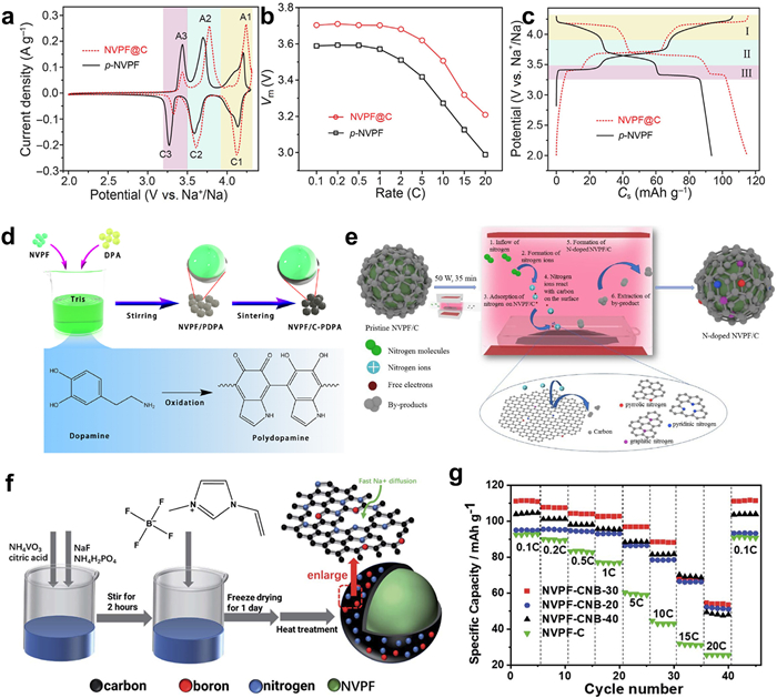
In addition, establishing electron transport with high electronic conductivity is a crucial method for optimizing the electrode structure. Coated on the surface can ameliorate the conductibility for ion/electron and enhance the structural stability, resulting in the high performance of NVPF [89]. Using carbon as a coating layer has been considered as a valuable method for enhancing electronic conductivity. For instance, Gu et al. [90] synthesized a carbon-coated NVPF using agarose as a novel carbonaceous precursor by ball-milling process, resulting in a high working voltage, which means a higher energy density than an uncoated one. The electrochemical test found that the middle voltage and energy density have increased to 3.71 V and 428.5 Wh/kg, respectively, higher than that of uncoated NVPF (3.59 V and 336.0 Wh/kg, respectively) (Figs. 5a–c).
Figure 5
Figure 5.
(a) CV patterns at scan rate of 0.1 mV/s, (b) middle voltage variations of NVPF@C and p-NVPF and (c) alvanostatic charge-discharge curves at 0.1 C. Reproduced with permission [90]. Copyright 2020, Elsevier. (d) Synthesis process of NVPF/C-PDPA. Reproduced with permission [94]. Copyright 2018, American Chemical Society. (e) Formation mechanism diagram of N-doped NVPF/C. Reproduced with permission [96] Copyright 2021, Elsevier. (f) Schematic illustration of the fabrication process of NVPF-CNB. (g) Its rate performance. Reproduced with permission [99] Copyright 2022, Royal Society of Chemistry.
A carbon coating layer with heterogeneous atomic doping can increase active electronic sites and defects in the carbon layer, effectively improving the migration rate of ions and electrons [91,92]. For example, N-doped carbonaceous materials can efficiently fabricate the additional active sites to enhance the ion diffusion, while sulfur-doped carbonaceous materials can increase the defect degree to improve the electrochemical performance [93]. Dopamine, a natural nitrogenous-rich compound, was used to fabricate the complete and uniform N-doped carbon layer covered NVPF (Fig. 5d), which could prevent the corrosion of NVPF in the electrolyte and produce more active sites, resulting in superior capacity retention of 95.8% after 800 cycles at 10 C [94]. In addition, plasma technology is also an effective method to generate defects on the surface of materials, which could quickly produce doping and defects on the surface of materials [95]. For example, Yi et al. [96] applied the plasma-enhanced chemical vapor deposition (PECVD) method to realize the N-doping carbon-coated NVPF using N2 gas as an N source (Fig. 5e). The defected carbon layer with multi-type N can provide more active sites and shorten the transmission path for Na+, resulting in higher electrochemical performance. It delivered a high-rate performance of 109.8 mAh/g at 5 C and excellent cyclic performance at 10 C, with high-capacity retention of 91.4% after 1000 cycles.
Dual atom doping can also improve the electrochemical performance of the material, which can combine the advantages of the two doped atoms and achieve optimal performance improvement through a synergistic effect [97,98]. For example, nitrogen and boron co-doped carbon-coated NVPF were prepared using 1-vinyl-3-methyl imidazole tetrafluoroborate as nitrogen and boron sources (Fig. 5f) [99]. The composite delivered excellent rate capacities of 99 mAh/g and 90 mAh/g at 5 C and 10 C, respectively (Fig. 5g). This dual atom doping strategy not only enhances the active sites but also generates a more stable carbon coating layer, improving the cyclic stability of NVPF.
Graphene or graphene oxide can enhance electronic conductivity and increase the contact area between active material and electrolyte, improving electrochemical performance. Generally, the introduction of graphene into the electrode could form a highly connected network with the active material, enhancing electronic transmission [100,101]. Li et al. [102] synthesized NVPF@rGO nanoparticles by precipitation followed by a solid-state method using GO as a template (Fig. 6a). The flake-shaped secondary particles with micron-sized assembled by nanoscale primary grains (about 50–100 nm) were obtained (Fig. 6b and c). They further found that the introduction of GO can limit crystal growth and overcome the agglomeration of NVPF. It delivered a high initial discharge capacity of 123 mAh/g at 0.5 C and excellent capacity retention of 64% after 5000 cycles (Fig. 6d). Besides, modified graphene has also been investigated. The nitrogen-doped graphene was fabricated by irradiating and heating at the microwave oven in the NH3/Ar atmosphere. After that, the nitrogen-doped graphene encapsulated NVPF@C was synthesized by the sol-gel method (Fig. 6e). After nitrogen-doped, the degree of graphitization was improved. As the cathode for SIBs, this material has reached high-capacity retention of 96.5% after 300 cycles at 10 C due to the formation of conductive networks by nitrogen-doped graphene and carbon coating layer [103]. In addition, Hu et al. developed two hydrothermal strategies to fabricate the dually decorated NVPF by in-situ formed carbon and 3D graphene (NVPF/C@3DG) (Fig. 6f) [104]. Fig. 6g shows a uniform amorphous carbon layer and 3D graphene, providing a large surface area, diminishing Na+ transfer path, and delivering an initial discharge capacity of 123.6 mAh/g at 0.2 C and stable cycle performance with high-capacity retention of 82.9% after 1000 cycles at 15 C.
Figure 6
Figure 6.
(a) Schematic diagram of the preparation of well-dispersed NVPF@rGO. SEM (b) and TEM (c) of NVPF@rGO. (d) Rate performance of NVPF@rGO. Reproduced with permission [102]. Copyright 2020, Royal Society of Chemistry. (e) TEM image of NG-NVPF@C. Reproduced with permission [103]. Copyright 2019, Elsevier. (f) Schematic diagram of the synthesis of NVPF/C@3DG composite. (g) HRTEM of NVPF/C@3DG composite. Reproduced with permission [104]. Copyright 2020, WILEY-VCH. (h) Schematic of Na+ and electron transportation, SEM and TEM of NVPF@C/CNTs. Reproduced with permission [107]. Copyright 2019, Frontiers. (i) SEM image of NVPF-SWCNT. Reproduced with permission [108]. Copyright 2019, Royal Society of Chemistry.
Carbon nanotubes (CNTs) have attracted much attention due to their strong mechanical support and high electronic conductivity in developing high-performance electrode materials [105,106]. Guo et al. [107] prepared an NVPF@C/CNTs tetragonal microparticles by a simple hydrothermal method (Fig. 6h). The CNTs can improve the conductivity and suppress the NVPF particle growth. Thus, the cathode achieved a high initial discharge capacity of 120.2 mAh/g at 0.1 C. Otherwise, Liu et al. [108] synthesized the NVPF and single-walled carbon nanotube (NVPF-SWCNT) composites by solvothermal method. Here, the SWCNT can lead to generate the pure phase and enhance the crystallinity of material as a seed crystal (Fig. 6i). As a result, the NVPF-SWCNT maintained capacity retention of 96% at 10 C after 500 cycles.
4.3
Optimizing the electrolyte components
Besides, designing the crystal structure and adjusting the electrode structure, optimizing the electrolyte components is considered another strategy to enhance the electrochemical performance [19,109]. Electrolyte, an essential battery component, can provide a substrate for ion transmission between the cathode and anode [110]. Currently, the strategies to optimize the electrolyte components for high-performance SIBs include: (1) Using a novel electrolyte or adopting the unique ratio of electrolyte components to improve the electrochemical properties of electrode materials by optimizing the ionic conductivities and viscosities [111,112]. (2) Adding electrolyte additives to improve the cyclic stability by forming a stable electrolyte interface at the electrolyte-electrode interface [113].
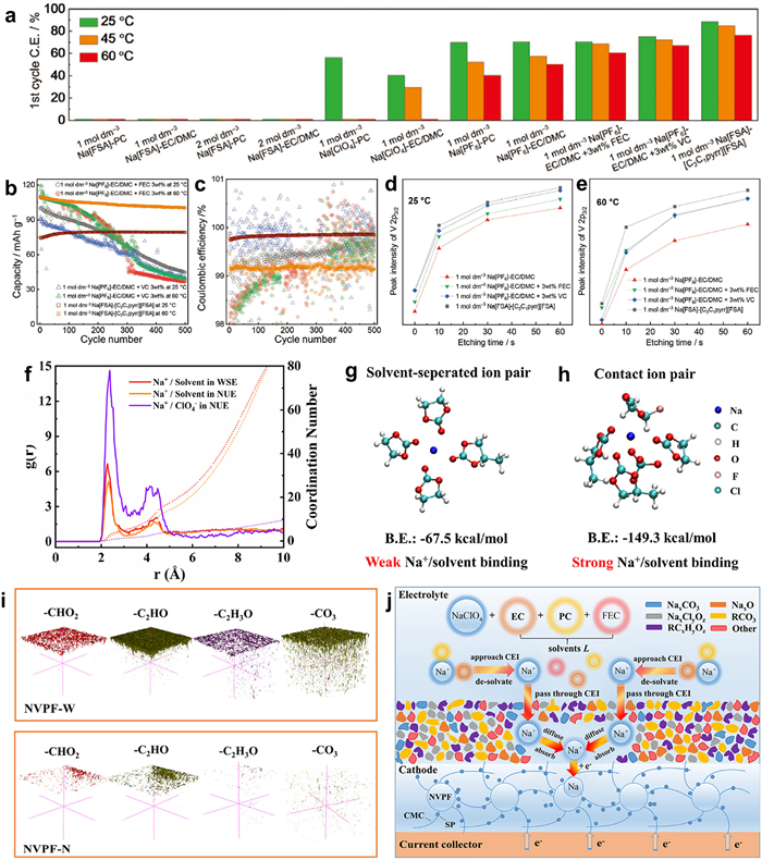
Generally, the electrolyte would continuously decompose at high voltage, leading to capacity fading and low Coulombic efficiency. Hwang et al. selected a series of different electrolyte composites to study the electrochemical performance of NVPF at high voltage [114]. They found that the ionic liquid electrolyte of Na[FSA]-[C3C1pyrr][FSA] presents the highest initial Coulombic efficiencies at various temperatures (Fig. 7a). Besides, this study indicated that the additives of fluoroethylene carbonate (FEC) and vinylene carbonate (VC) could improve the specific capacity and suppress the degradation of organic electrolyte, but the capacity retention is still un-improved. Moreover, the ionic liquid electrolyte, such as Na[FSA]-[C3C1pyrr][FSA] system, presented not only supreme stability but also higher rate performance at high temperatures (Figs. 7b and c). Furthermore, the CEI thickness was evaluated by the intensity of the V 2p3/2. As shown in Figs. 7d and e, the thickness of the CEI layer in Na[FSA]-[C3C1pyrr][FSA] electrolyte shows the thinnest at room/high temperature. This result can be attributed to producing a thin and robust CEI layer by the oxidation of FSA− in the ionic liquid electrolyte, which is conducive to obtaining good electrochemical performance under high voltage range and high-temperature conditions.
Figure 7
Figure 7.
(a) The first cycle Coulombic efficiency for the electrolytes in this study measured at a C-rate of 0.1 C and a cutoff voltage of 2.0 V/4.3 V. Cycle performance (b) at 25 and 60 ℃ and (c) the corresponding Coulombic efficiency plots of the NPVF-C electrode with the selected electrolytes. The peak intensity changes against etching time at (d) 25 ℃ and (e) 60 ℃. Reproduced with permission [114]. Copyright 2020, WILEY-VCH. (f) Na+ radial distribution function obtained from quantum chemistry calculations in the two electrolytes. Most probable solvation structure extracted from AIMD simulations together with their binding energy values. (g, h) The most probable solvation structure extracted from AIMD simulations and their binding energy values. (i) TOF-SIMS 3D-mapping images of several representative secondary ion fragments obtained from the NVPF cathodes after cycling. (j) Schematic illustration of the NVPF/interface/electrolyte system in the weakly-solvating electrolyte. Reproduced with permission [115]. Copyright 2021, Elsevier.
Deng et al. [115] reported a high-voltage NVPF cathode with fast charge transfer kinetics at low temperatures by self-optimizing weak solvation effects. According to the ab initio molecular dynamics calculation and quantum chemistry calculations, the weakly-solvating structure can be formed in a low-concentration electrolyte (0.3 mol/L NaPF6), resulting in a fast Na+ desolvation process (Figs. 7f–h). Besides, the TOF-SIMS test confirmed the formation of a dense and uniform CEI layer (Fig. 7i) and illustrated by Fig. 7j, which presents weak solvation effects that could deliver optimizing interface chemistry. The electrochemical measurement showed the best rate capacity (101.6 mAh/g at 1 C) and excellent cycling performance (capacity retention of 93.4% after 1000 cycles at 1 C) at −25 ℃.
5.
Summary and outlook
Na3V2(PO4)2F3 with NASICON structure has been attracted more attention as promising cathode material for SIBs due to their high operating potential and excellent structural stability. In this review, we have summarized the several synthetic strategies for enhancing electrochemical performance from the viewpoint of the relationship between structure and electrochemical properties. Besides, the advanced strategies in recent years in enhancing the ion transfer diffusion and electrical conductivity of NVPF for SIBs are further in-depth analyzed, which include (1) designing the crystal structure, (2) adjusting the electrode structure, and (3) optimizing the electrolyte components. Although some development has been investigated to improve the electrochemical performance of NVPF, there are still many challenges that should be solved.
(1) Design and rational self-assembly of multi-levered architectures for NVPF is a promising strategy. Because this structure and morphology of NVPF play a significant role in the electrochemical performance. For instance, the multi-levered architectural NVPF can avoid the serious chalking and agglomeration of nano-powders during the charge and discharge process while maintaining the excellent properties of the nanostructure. Therefore, the fabrication of NVPF with multi-levered architectures is necessary.
(2) Crystal growth engineering for NVPF applications is still inadequate. The relationship between structure and electrochemical properties must be established. The mechanisms of crystal growth for NVPF have only been investigated in a few studies, and the theoretical model of growing crystal facets for NVPF is still unclear. Therefore, it is necessary to find a model to better understand the relationship between crystal growth engineering and electrochemical performance.
(3) Doping strategies also need to be further investigated. However, most research about ion-doping are mainly focused on the experimental stage. The theoretical analysis is still lacking. With the development of quantum-mechanical calculation, a first-principles calculation based on the DFT methods has received much attention, especially high-throughput screening. Thus, the combination of experiments and theoretical analyses will significantly promote the development of an element doping strategy.
(4) It is highly desired to develop new electrolyte components to utilize NVPF in a broad temperature range. As previously reported, the ionic liquid performs at a wide temperature range. Thus, a similar strategy could be developed, not just for ionic liquids. Besides, creating a suitable solid-state electrolyte is another promising strategy to improve the electrochemical performance of NVPF at high-temperature because of their safety. Thus, more electrolyte studies are required to obtain utilization at a wide temperature range.
Declaration of competing interest
The authors declare that they have no known competing financial interests or personal relationships that could have appeared to influence the work reported in this paper.
Acknowledgments
The authors acknowledge the National Natural Science Foundation of China (No. 91961126). In addition, the authors thank Jiangsu Development & Reform Commission and Changzhou Development and Reform Commission for their support.
Supplementary materials
Supplementary material associated with this article can be found, in the online version, at doi:10.1016/j.cclet.2022.107978.
S. Liu, L. Wang, J. Liu, et al., J. Mater. Chem. A 7 (2019) 248–256. doi: 10.1039/c8ta09194c
[109]
G. Yan, D. Alves-Dalla-Corte, W. Yin, et al., J. Electrochem. Soc. 165 (2018) A1222-A1230. doi: 10.1149/2.0311807jes
[110]
H. Pan, Y.S. Hu, L. Chen, Energy Environ. Sci. 6 (2013) 2338–2360. doi: 10.1039/c3ee40847g
[111]
A. Ponrouch, R. Dedryvère, D. Monti, et al., Energy Environ. Sci. 6 (2013) 2361–2369. doi: 10.1039/c3ee41379a
[112]
M.K. Sadan, H. Kim, C. Kim, et al., J. Mater. Chem. A 8 (2020) 9843–9849. doi: 10.1039/d0ta02721a
[113]
Y. Wang, Y. Zhang, S. Wang, et al., Adv. Funct. Mater. 31 (2021) 2102360. doi: 10.1002/adfm.202102360
[114]
J. Hwang, K. Matsumoto, R. Hagiwara, Adv. Energy Mater. 10 (2020) 2001880. doi: 10.1002/aenm.202001880
[115]
L. Deng, K. Goh, F.D. Yu, et al., Energy Storage Mater. 44 (2022) 82–92. doi: 10.1016/j.ensm.2021.10.012
Figure 1
Fig. 1. (a, b) Structural characterization of NVPF. Reproduced with permission [29]. Copyright 2018, Elsevier. (c) Coordination polyhedral around the Na site and possible examples for a long-range ion migration path along the x, y, and z directions. Reproduced with permission [30]. Copyright 2014, American Chemical Society. (d) Ex situ23Na NMR spectra of NVPF electrodes at different states of charge. Reproduced with permission [31]. Copyright 2014, American Chemical Society. (e) Charge and discharge profile of NVPF. (f) Integrated spin as a function of integration radius around vanadium ions for NaxVPF at x = 3 and x = 1. Reproduced with permission [32]. Copyright 2012, Royal Society of Chemistry.
Figure 2
(a) The doping element on the Periodic Table of Elements. Rate performance of ion-doped NVPF: (b) Li+. Reproduced with permission [48]. Copyright 2018, Elsevier; (c) K+. Reproduced with permission [50]. Copyright 2021, Institute of Process Engineering, Chinese Academy of Sciences; (d) Ti2+. Reproduced with permission [51]. Copyright 2018, Elsevier; (e) Y3+. Reproduced with permission [52]. Copyright 2017, Royal Society of Chemistry; (f) Zr4+. Reproduced with permission [56]. Copyright 2021, Wiley-VCH; (g) Mn2+. Reproduced with permission [54]. Copyright 2021, Elsevier; (h) Fe2+. Reproduced with permission [58]. Copyright 2021, Elsevier; (i) Na+. Reproduced with permission [59]. Copyright 2021, Wiley-VCH; (j) Br−. Reproduced with permission [63]. Copyright 2022, Wiley-VCH.
Figure 3
(a) Schematic diagram of the growth of the NVPF samples. (b) Calculated structures (side view) of (001), (100), and (010) surfaces of the NVPF crystal. Electrochemical performance of NVPF@KB at different pH values: (c) Charge and discharge curves, (d) Rate capacity. (e) Cycle performance of NVPF@KB at pH 3. Reproduced with permission [75]. Copyright 2019, American Chemical Society. (f) XRD patterns and enlarged XRD patterns. (g) The schematic diagram shows the correlation between the change in diffraction peaks and the crystal evolution of NVPF and the corresponding atomic structures of the (001), (110), and (110) facets (e). (h) Schematic diagram showing the difference in Na+ migration in the original NVPF (a1) and NVPF grown along with the (110) axis (a2). SEM images of NVPF (i) and NVPF adding NaCl (j). Rate capacity (k) and cycle performance (l) for NVPF@rGO. Reproduced with permission [76]. Copyright 2020, Royal Society of Chemistry.
Figure 4
(a) Schematic illustration of polyol-based NVPF/C synthesizing protocol. SEM (b) and TEM images (c) of NVPF/C nanoparticles. (d) Charge and discharge curves of NVPF/C. Reproduced with permission [79]. Copyright 2019, Springer Nature. (e) Schematic of the preparation of NVPF-H@cPAN. SEM (f, g) and TEM images (h) of NVPF-H@cPAN. (i) Schematic of Na+ and electron transportation. (j) Its rate capacity. Reproduced with permission [86]. Copyright 2021, Elsevier. (k) Schematic diagram of the synthesis process of CQDs-modified NVPF. SEM (l, m) and TEM images (n) of CQDs-modified NVPF. (o) Its rate capacity. Reproduced with permission [87]. Copyright 2020, Royal Society of Chemistry. (p) Schematical representation of the fabrication of NVPF@CD nanocomposite and magnified representation of the electronic and ionic transport within the CMK-3 channels. SEM (q) and TEM images (r) of NVPF@CD nanocomposite. (s) Its rate capacity. Reproduced with permission [88] Copyright 2016, American Chemical Society.
Figure 5
(a) CV patterns at scan rate of 0.1 mV/s, (b) middle voltage variations of NVPF@C and p-NVPF and (c) alvanostatic charge-discharge curves at 0.1 C. Reproduced with permission [90]. Copyright 2020, Elsevier. (d) Synthesis process of NVPF/C-PDPA. Reproduced with permission [94]. Copyright 2018, American Chemical Society. (e) Formation mechanism diagram of N-doped NVPF/C. Reproduced with permission [96] Copyright 2021, Elsevier. (f) Schematic illustration of the fabrication process of NVPF-CNB. (g) Its rate performance. Reproduced with permission [99] Copyright 2022, Royal Society of Chemistry.
Figure 6
(a) Schematic diagram of the preparation of well-dispersed NVPF@rGO. SEM (b) and TEM (c) of NVPF@rGO. (d) Rate performance of NVPF@rGO. Reproduced with permission [102]. Copyright 2020, Royal Society of Chemistry. (e) TEM image of NG-NVPF@C. Reproduced with permission [103]. Copyright 2019, Elsevier. (f) Schematic diagram of the synthesis of NVPF/C@3DG composite. (g) HRTEM of NVPF/C@3DG composite. Reproduced with permission [104]. Copyright 2020, WILEY-VCH. (h) Schematic of Na+ and electron transportation, SEM and TEM of NVPF@C/CNTs. Reproduced with permission [107]. Copyright 2019, Frontiers. (i) SEM image of NVPF-SWCNT. Reproduced with permission [108]. Copyright 2019, Royal Society of Chemistry.
Figure 7
(a) The first cycle Coulombic efficiency for the electrolytes in this study measured at a C-rate of 0.1 C and a cutoff voltage of 2.0 V/4.3 V. Cycle performance (b) at 25 and 60 ℃ and (c) the corresponding Coulombic efficiency plots of the NPVF-C electrode with the selected electrolytes. The peak intensity changes against etching time at (d) 25 ℃ and (e) 60 ℃. Reproduced with permission [114]. Copyright 2020, WILEY-VCH. (f) Na+ radial distribution function obtained from quantum chemistry calculations in the two electrolytes. Most probable solvation structure extracted from AIMD simulations together with their binding energy values. (g, h) The most probable solvation structure extracted from AIMD simulations and their binding energy values. (i) TOF-SIMS 3D-mapping images of several representative secondary ion fragments obtained from the NVPF cathodes after cycling. (j) Schematic illustration of the NVPF/interface/electrolyte system in the weakly-solvating electrolyte. Reproduced with permission [115]. Copyright 2021, Elsevier.

 DownLoad:


 下载:
下载:


