Citation:
Lei Xie, Chaoqin Huang, Zhaofeng Liang, Hongbing Wang, Zheng Jiang, Fei Song. In-Situ HP-STM and Operando EC-STM Studies of Heterogeneous Catalysis at Interfaces[J]. Chinese Journal of Structural Chemistry,
2022, 41(10): 221002.
doi:
10.14102/j.cnki.0254-5861.2022-0136
In-Situ HP-STM and Operando EC-STM Studies of Heterogeneous Catalysis at Interfaces
作者简介:Lei Xie received her PhD degree in materials science and technology from Tongji University in 2019. Afterwards, she became an engineer at Shanghai Advanced Research Institute, Chinese Academy of Sciences. Her research interest focuses on the characterization of physical and chemical properties of surfaces, especially by scanning tunneling microscopy;
Fei Song received his PhD degree in Condensed Matter Physics from Zhejiang University and Aarhus University in 2009. He then moved to Norwegian and the Netherlands for postdoctoral research. He became an independent research fellow at Shanghai Institute of Applied Physics, Chinese Academy of Sciences in 2015, and is now a full professor at Shanghai Synchrotron Radiation Facility. His research interest is mainly focused on novel nanostructures characterization and manipulation at surface and interface;
Shanghai Synchrotron Radiation Facility, Shanghai Advanced Research Institute, Chinese Academy of Sciences, Shanghai 201204, China
2.
Shanghai Institute of Applied Physics, Chinese Academy of Sciences, Shanghai 201000, China
3.
University of Chinese Academy of Sciences, Beijing 101000, China
Author Bio:Lei Xie received her PhD degree in materials science and technology from Tongji University in 2019. Afterwards, she became an engineer at Shanghai Advanced Research Institute, Chinese Academy of Sciences. Her research interest focuses on the characterization of physical and chemical properties of surfaces, especially by scanning tunneling microscopy;Fei Song received his PhD degree in Condensed Matter Physics from Zhejiang University and Aarhus University in 2009. He then moved to Norwegian and the Netherlands for postdoctoral research. He became an independent research fellow at Shanghai Institute of Applied Physics, Chinese Academy of Sciences in 2015, and is now a full professor at Shanghai Synchrotron Radiation Facility. His research interest is mainly focused on novel nanostructures characterization and manipulation at surface and interface;
Received Date:
25 May 2022 Accepted Date:
13 June 2022 Available Online:
25 October 2022
Abstract:
Heterogeneous catalysis taking place at solid interfaces plays a crucial role not only in industrial chemical production, energy conversion but also in fundamental research. The dynamic evolution of surface morphology and composition requires full understanding especially under realistic reaction conditions. To this end, conventional scanning tunneling microscopy (STM) has been integrated with high pressure cell and electrochemical cell, forming high pressure (HP) STM and electrochemical (EC) STM for the in-situ/operando characterization at solid-gas and solid-liquid interfaces with atomic resolution, respectively. In this review, we attempt to give a brief introduction to the development and working principle of these two techniques and subsequently summarize several representative progresses in recent days. The dynamic changes in active sites, surface reconstruction, absorbates alteration and products formation are directly characterized in a combination with other surface sensitive technologies. The correlation between surface structures and catalytic performance as well as the underlying mechanism can thus be unraveled, which provides insights into the rational design and optimization of catalysts.
Heterogeneous catalysis is a crucial process for the fabrication of tremendous industrial chemicals and energy conversion, which always takes place among different phases, especially at solid-gas and solid-liquid interfaces.[1-4] While developing efficient and improved catalysts with high selectivity is demanding but still challenging. In order to correlate the performance of catalyst with its geometric and electronic properties, various characterization methods are required. Considering that the catalytic active sites are always constrained within the metal atoms and defects on surfaces rather than bulk, it is of great importance to unravel the evolution of surface and subsurface states. Many surface-sensitive techniques have thus been utilized to fulfill this issue. Among them, scanning tunneling microscopy (STM) provides solid results of superficial topography as well as the density of electronic states with atomic resolution in real space, [5-9] which is critical for the determination of precise active sites, intermediate states and further the reaction mechanism.
Tremendous work has been performed under well-defined ultrahigh vacuum (UHV) conditions on model systems to eliminate the impact of undesired atmosphere. Despite that much knowledge has been learned from UHV studies, most realist catalytic reactions inevitably happen at ambient/high pressure (above 1 mTorr) or even at solid-liquid interfaces, which is far more complicated, leading to the so-called pressure and material gaps.[10] The catalysts undergo a thermal dynamic equilibrium with reactant environments which always cause reconstruction of geometric and electronic structures of surfaces compared with that at UHV conditions.[11] Therefore, high pressure scanning tunneling microscopy (HP-STM) has been developed to overcome the pressure gap and in the meantime also endures high temperatures, where the thermal catalytic reactions occur in the limited reaction cell.
On the other hand, the detailed understanding of electrochemical procedures is important for industries like batteries, fuel cells, solar cells, electroplating, corrosion prevention, electro-organic synthesis, and sensors. The catalytic reactions specifically take place at solid-liquid interface, which plays an important role in controlling the electron-transfer reaction.[12] The detection of electrochemical interface can be performed via electrochemical scanning tunneling microscopy (EC-STM) in the environment of electrolytes, by recording the chemical and geometric conversion of interface such as the adsorption and desorption of ions and organic molecules, underpotential deposition (UPD) as well as catalytic reactions under potential control.
By means of these advanced techniques, in situ STM studies (where catalytic reaction occurs at ambient pressure while is still much smaller than in the real industrial reactions) and operando STM studies (where catalytic reaction happens at the pressure near to real catalytic condition or in liquids) can be conducted, where the dynamic changes of model catalysts under working conditions and during whole catalytic processes are directly recorded at interfaces. Such real-time and real-space observation gives detailed insights on the formation of absorbates, intermediates, products, and the conversion of actives sites, which is pivotal for catalytic performance.
In this review, we briefly describe the schematic construction and working principle of both HP-STM and EC-STM. Thereafter, recent progresses of in situ/operando STM inspections on various gaseous and electrochemical catalytic processes are systematically emphasized. Furthermore, applications of these techniques in combination with other surface science technology, for instance, near ambient pressure X-ray photoelectron spectroscopy (NAP-XPS), are also introduced. The abovementioned synergetic methods provide local compositional evolution of surface and subsurface simultaneously, which is in complementary with STM studies at atomic scale, permitting the comprehensive understanding of dynamic catalysis process and elucidation of reaction mechanism.
DEVELOPMENT AND WORKING PRINCIPLE OF HP-STM AND EC-STM
An Overview of STM. After the first invention of STM instrument by Binnig and Rohrer in early 1980s, [13] it has become one of the most important and widely used standard techniques in the field of surface science. Based on quantum mechanics, there exists a possibility for electrons to tunnel through a potential barrier.[14] When the distance between conductive tip and metal/semiconductor surfaces is rather small (down to several angstrom), a tunneling current would be generated once a voltage is applied to the junction. The current is determined by the following formula: I∝Vρs(0, EF)e−2kz, where ρs(k, E) represents for the local density of states of the sample and tip, and z is the distance between tip and sample. As the tunneling current is exponential to z, a tiny change on distance could result in a vast variation of the corresponding current.[1] Therefore, with the help of piezoelectric materials controlling the tip movement and feedback loop of electronics, surface morphology can then be directly observed at single atom level. In general, STM can be operated either in constant-current or constant-height mode. In constant-current mode, the difference between the measured current and the setpoint value gives feedback adjustments to the vertical position of the tip by varying the applied voltage on z-piezo for maintaining the tunneling current constant. Hence the local features of surface topography can be obtained upon scanning with striking contrast. While in the constant-height mode, the height of tip keeps unchanged and the recorded tunneling current varies according to the fluctuation of surface. The latter one is less utilized for it requires a rather flat local area and represents for little density of states. Another powerful tool is vertical/lateral STM manipulation, which endows the movement of single atoms/molecules in a desired manner, rearranging self-assembled structures, breaking hydrogen and covalent bonds, and even inducing chemical reactions.[15-19] Scanning tunneling spectroscopy provides plots of current as a function of applied bias, giving information on local electronic states and vibrational properties.[17, 20-22]
Development and Working Principle of HP-STM. Tremendous works have been performed under UHV conditions to eliminate the contamination of environment and in the meantime preserve the high resolution in the determination of surface structures, on-surface synthesis processes as well as study of numerous chemical and physical properties.[5-9, 15-22] In addition, experiments in atmospheric environment or in solid-liquid systems have also been conducted for rational design of functional supramolecular architectures and dynamic fabrication of polymers, [23-26] whereas the in-situ characterization of surface evolution under real catalytic condition or during the process of catalysis has become a strong demand as it exhibits huge differences compared with the UHV results. Afterwards, many efforts have been devoted to extending the facility to in the meantime endure higher pressures during the past few decades. In early stages, scientists just simply filled the STM chamber with reactant gas to mimic the catalytic environment, [27] while the large number of gas molecules cause many problems, like difficulty in annealing the sample, long recovery to UHV state, shrinking the lifetime of STM head and so forth. Recently, the design of chamber-in-chamber prevails in creating catalytic atmosphere while scanning, for it provides isolation of reaction cell contained in the main chamber. The schematic illustration of this design is shown in Figure 1a where the STM block is suspended by springs with the high-pressure cell volume about 0.5land the pressure limit up to 1000 mbar.[28]
Figure 1
Figure 1.
(a) A high-pressure STM and its mounting and suspension system. Reproduced with permission form ref. 28. Copyright 2001 AIP Publishing. (b) Schematic illustration of a HP-STM cell with flow reactant.
(c) and (d) Shielding dome and sample heating. Reproduced with permission form ref. 11. Copyright 2013 AIP Publishing.
Latest progress[11] has been made as shown in Figure 1b where the main feature lies in the separation of reactor containing hot gas with room-temperature scanning system, guaranteeing the ideal working condition for scanning tube and approach motor. From a close inspection (Figure 1c), we can see that a shielding dome with a tiny aperture designed for the movement of tip keeps the STM room away from hot gas annealed by radiative heater, minimizing the excess thermal drift to obtain atomic resolution STM images during in-situ experiments (Figure 1d). In addition, the reaction cell also consists of gas inlet and outlet pathways, generating a purified gas flow above the sample surface, which makes the identification of products and detection of reactant changes possible by mass spectrometer. Besides, by virtue of differential pumping system, the gas pressure in the reactor can reach 1 bar while the UHV chamber remains in an acceptable high vacuum level. Moreover, the system can achieve elevated temperature up to ∼230 ℃ with atmosphere. Moreover, a specially designed Reactor STM for the observation of catalytic reactions can be operated from UHV to 6 bar and from room temperature to 600 K, where a mass spectrometer is combined to correlate the reactivity directly to surface structure.[29] By this means, HP-STM instrument nowadays renders in situ/operando visualization of the structural transformation including the restructuring of surface and migration of single atoms or vacancies by fast scanning of consecutive STM images with atomic resolution.
Development and Working Principle of EC-STM. Many industry related processes among condensed phases, encompassing corrosion, dissolution, etching of silicon wafers, biological processes, heterogeneous catalysis, reaction in batteries and so on, call for the detailed understanding of local surface structure and dynamics of electrochemical processes at single atom level as well. Except for the abovementioned HP-STM operated at solid-gas interface, liquid STM combined with electrochemical cell has also been developed for operando studies at solid-liquid interface under reaction conditions.[1]
The electrochemical double layer shown in Figure 2a is the fundamental model concept in terms of liquid-solid interactions.[30] All the electrochemical processes start with the adsorption of ions from electrolyte onto the surface of electrode. Within the inner Helmholtz plane, the absorbed anions interact strongly with the positive electrode surface with charge and in the outer Helmholtz plane the interaction is relatively weak so that the hydration sphere keeps intact. The EC-STM provides geometric insight at atomic level into the structure of the substrate and the adsorbed anion layers as a function of electrode potential in harsh electrolyte environment.[30-33]
Figure 2
Figure 2.
(a) Simple Grahame model of the electrochemical double layer (a) and adsorption of organic cations after a charge reversal due to a full monolayer of specifically adsorbed anions. Reproduced with permission form ref. 30. Copyright 2012 Swiss Chemical Society. (b) Schematic diagram of the EC-STM setup and working principle. Reproduced with permission form ref. 30. Copyright 2018 John Wiley and Sons.
At first, the solid-liquid STM possessed only two electrodes, namely tip and surface without a reference electrode (RE), thus the charge transfer can occur at the tip, ruining the stability of the system. Afterwards, RE was introduced forming a three-electrode system. Whereafter, a four-electrode setup was invented by adding another counter electrode (CE). A schematic diagram of EC-STM setup mostly used nowadays is shown in Figure 2b, where an STM is incorporated with electrolytic environment under potential control.[33] The potentiostat is in connection with all electrodes, namely working electrode one (WE 1, the substrate), working electrode two (WE 2, the STM tip), RE and CE, and the potential of WE 1 and WE 2 with respect to RE can be tuned independently. Unlike conventional STM, the tunneling current generated between tip and sample in EC-STM is inevitably accompanied by faradaic current through the tip. Thus, in order to eliminate the effect from faradaic current, the tip has been largely insulated by polymers, leaving only the metal apex exposed for the generation of tunneling current (inset of Figure 2b).[34, 35] Besides, the samples are usually prepared through flame annealing or electrochemical etching to obtain fresh surfaces, which is different from the UHV and HP-STM experiments by cycled treatment of sputtering and annealing.[30]
In addition to the above mentioned in situ HP-STM, operando EC-STM, many other advanced techniques especially those with chemical sensitivity, like XPS, infrared reflection absorption spectroscopy, transmission electron microscopy, X-ray absorption spectroscopy (XAS), atomic force microscopy (AFM) etc. have also been integrated to achieve a comprehensive understanding on the dynamics of catalytic reaction process.[33, 36-41] Owing to the combination of experiments with density functional theory (DFT) calculations and molecular dynamic simulations, the underlying catalytic mechanism can further be unraveled, paving the way for optimization of catalyst design.
IN-SITU/OPERANDO HP-STM STUDIES OF HETEROGENOUS CATALYSIS AT SOLID-GAS INTERFACE
HP-STM has been verified as a valuable tool to bridge the pressure gap in resolving the catalytically active surface at atomic level after dynamically adapting to the surrounding environment. Herein, in terms of the composition of catalysts, we provide a systematic review on the in-situ HP-STM studies about the adsorption behavior and typical catalytic reactions (CO oxidation, ethylene oxidation, Fischer-Tropsch synthesis, etc.) performed on single crystal metal surface, bimetallic surface, oxide/metal inverse catalysts as well as on semiconductors. Other complementary surface-sensitive methods and theoretical calculations are necessarily included for the interpretation of underlying mechanism.
HP-STM Studies on Single Crystal Metal Surfaces
Catalytic reactions typically consist of various processes, such as the adsorption of reactants on surface, diffusion of absorbates and desorption of final products. The adsorption behavior of gas molecules is thus significantly important to investigate according to pressure alteration. CO molecules participate in a wide range of catalytic processes, like water-gas reaction, Fischer-Tropsch synthesis and CO oxidation, in resolving environmental issue. Moreover, it also brings the problem of active sites poisoning, where the adsorption structures and reaction properties need to be resolved. In this section, different single crystal metal surfaces are mentioned for they offer flat and ideal working bench for distinct determination of on-surface structures.
Pressure Dependent CO Adsorption on Pt Surfaces. Precious transition metal catalysts, like Pt, Pd, Rh, and so on, play inevitable role in many reactions.[42] CO adsorption processes on Pt based model catalysis surfaces have been extensively explored by in-situ HP-STM under a wide pressure range and the relative studies are listed as follows so as to give a thorough view.[43-49]
The adsorption of CO on Pt(111) in a pressure range from 10-6 to 760 Torr was investigated in equilibrium with gas phase.[47] A pressure-dependent hexagonal Moiré pattern alteration is observed as shown in Figure 3a i and ii at 10-2 and 760 Torr respectively, where the orientation of the absorbed lattice of CO molecules changes from a fixed 30° with respect to the high-symmetry direction to a commensurate (√19 × √19) R23.4°-13CO structure (see the corresponding model in iii and iv). Owing to the increasing CO-CO repulsion interactions, the CO adsorbate layer is continuously compressed with increasing pressure, resulting in a coverage variation as shown in the diagram of Figure 3a (v). Recently, by introducing defective-rich h-BN overlayer on Pt(111), Bao and co-workers have observed dynamic CO adsorption on confined metal substrate at pressure from UHV to 300 mbar. Interestingly, the h-BN top layer is transparent to STM imaging and the density of CO intercalation is higher than that on the bare Pt(111).[48]
Figure 3
Figure 3.
CO adsorption on Pt crystals. (a) STM images and corresponding models of CO Moiré superstructures on Pt(111) at room temperature. (ⅰ) Incommensurate structure at p = 10-2 Torr. (ⅱ) p = 720 Torr.
(ⅲ) Incommensurate model structure at 10-2 Torr. (ⅳ) Commensurate (√19 × √19) R23.4°-13CO structure at 720 Torr. (ⅴ) CO coverage θ on Pt(111) as a function of CO pressure. Reproduced with permission form ref. 47. Copyright 2004 American Chemical Society. (b) STM images of Pt(110) at different CO pressures at 373 K. (ⅰ) 10-7 mbar CO. (ⅱ) 10-6 mbar CO. (ⅲ) 10-5 mbar CO. (ⅳ) 10-2 mbar CO. (ⅴ) 1000 mbar CO. (ⅵ) zoomed in STM image at 1000 mbar CO. Reproduced with permission form ref. 45. Copyright 2003 AIP Publishing. (c) STM images of hex-Pt(100) surface at different CO pressures. (ⅰ, ⅱ) Large-scale and zoomed-in STM image at 5 × 10⁻⁹ Torr of CO. Step edges are marked with arrows. (ⅲ) Islands formed in 10-6 Torr of CO. (ⅳ) Adsorbed CO in equilibrium with the gas at 10-5 Torr. Reproduced with permission form ref. 43. Copyright 2009 American Chemical Society. (d) STM images of Pt(557) (ⅰ) at UHV condition. (ⅱ) under ~5 × 10⁻⁸ Torr of CO. (ⅲ) under 1 torr of CO. (ⅳ) Enlarged view of (ⅲ) showing the roughly triangular shape of the nanoclusters formed at 1 torr. Two of the clusters are marked with red lines. Reproduced with permission form ref. 50. Copyright 2010 The American Association for the Advancement of Science.
While for other Pt single-crystals, the situation is quite different where surface reconstructions occur on the underlaying substrates. Pt(110) surface originally exhibits the well-known (1×2) missing-row reconstruction in UHV conditions. After the introduction of CO at relatively low pressure of 10-7 mbar, the (1 × 2) to (1 × 1) surface reconstruction occurs (Figure 3b ⅰ) as CO binds to low-coordinated metal atoms thus lifting Pt atoms. Further increasing the pressure of CO to 10-3 mbar, kink densities start to propagate. At the pressure of 1 bar, a saturated (2 × 1)-p2mg-2CO layer is observed as a result of steric repulsion as shown in Figure 3b-ⅵ with the underlying Pt surface remaining as (1 × 1). Here the STM images were taken under 373 K facilitating the formation of equilibrated structures.[45] In the case of quasi hexagonal Pt(100) surface exposed to CO in Figure 3c, the topmost layer reconstruction is partially lifted at 5 × 10⁻⁹ Torr of CO (ⅰ and ⅱ), giving rise to clusters of Pt atoms aligned along the [01-1] direction. After increasing the pressure to 10-5 Torr, more clusters are formed into a square lattice (ⅳ). Based on both experimental and DFT calculation results, CO molecules are bound to Pt nanoclusters through a tilted on-top configuration.[43]
In order to narrow the gap with real industrial catalysts, stepped single-crystal surface with a high number of uncoordinated sites is especially investigated. After exposure to CO at 5 × 10⁻⁸ Torr, the initially straight step edges become wavy (Figure 3d ⅱ). When the pressure is increased to 0.1 Torr, Pt crystals break up into nanometer-sized clusters with triangular shapes (Figure 3d ⅲ and ⅳ). Interestingly, after evacuating CO gas, the surface reverts to the initial morphology, which is also confirmed by NAP-XPS results. This reversible pressure-dependent restructuring clearly demonstrates the pressure gap existing in catalysts and verifies the importance in in-situ characterization in the study of heterogeneous catalysis.[50] Recently, partially ordered periodic triangular Pt clusters on the Pt(557) surface after exposure to 1.4 mbar CO at 373 K is also observed. The disordered-ordered transition can be subtly controlled by temperatures.[51]
Other than Pt surfaces, CO adsorption studies on Rh(111), [52, 53] low-Miller-index Cu and Au surfaces[54-57] which exhibit weak interaction with absorbates have also been conducted by HP-STM. Moreover, an ordered (2 × 2)-CO structure is formed by CO2 dissociation on Rh(111).[58] Besides CO molecules, the adsorption of many other gas molecules like NO, [59] H2, [60] CO2, [61] ethylene[62] and the coadsorption of molecules[52] at high pressures are investigated as well, where the lateral repulsion and the absorbate-substrate interactions play crucial roles in the process.[63, 64]
Fischer-Tropsch Synthesis on Co(0001). Modern industrial technology focuses on the conversion of gas mixtures (mainly CO, H2 and CO2) to liquid fuels.[65] One of the most widely used techniques, Fischer-Tropsch synthesis (FTS), consists of many reactions in the formation of various hydrocarbons originating from the mixture of CO and H2 at a proportion of 1:2, which accounts for approximately 2% of the world production of gasoline. Co-based catalysts are verified to be the most efficient for its high selectivity to long saturated linear hydrocarbons and low cost, while the direct observation of final product under reaction condition is challenging.
Navarro and co-authors successfully monitor a Co(0001) catalyst during FTS via a special purpose reactor STM at 4 bar and 220 ℃.[66] After 40 min of reaction, surprisingly, the Co surface is covered with linear striped overlayer as shown in Figure 4a. The Fast Fourier Transform (FFT) image in the inset of Figure 4b clearly identifies the existence of periodic structures. The featured strips are thus assigned to linear hydrocarbon molecules synthesized during the reaction absorbed on terraces in a flat manner aligned in parallel. The grow mechanism is according to Schulz-Flory-Anderson (SFA) model[67] where the CH2 units are bonded at the steps forming chains. Importantly, the longer the chains, more residence time would the product stay on surface due to the stronger adsorption interaction.
Figure 4
Figure 4.
(a) STM topography image of the cobalt surface at 221 ± 10 ℃, 40 min after switching to a reactive 1:2:2 mixture of carbon monoxide, hydrogen and argon at 4 bar total pressure. (b) Enlarged view region indicated by the dashed rectangle in (a), where the internal structure attributed to the individual alkane molecules produced during reaction and self assembled on the Co(0001) surface can be seen. The blue lines serve as a guide to indicate the arrangement of the individual linear hydrocarbons. Inset: Fourier transform, which reflects the main periodic structures in the image. Green circles highlight the peaks corresponding to the periodicity of the striped pattern (1.8 ± 0.3 nm). Pink circles highlight the periodicity of the individual molecules within the stripes (0.46 ± 0.04 nm). c, Histogram of the period of the striped pattern in images a and b, expressed as n (number of carbon atoms of the alkane molecules). Reproduced with permission form ref. 66. Copyright 2016 Springer Nature. (d) TOFs of the individual hydrocarbon products obtained with the annealed and the sputtered surface, from GCs recorded after 1 h and 5 h.
(e) The annealed Co(0001) sample in 950 mbar syngas, H2: CO = 2:1, 493 K; image recorded 4.5 h after the start of the experiment. (f) The annealed Co(0001) sample in 200 mbar syngas, H2: CO = 2:1, 493 K. (g) The same surface area 20 min later. Arrows are drawn for better visualization of the step edge motions. Scale bars, 20 nm. Reproduced with permission form ref. 69. Copyright 2019 Springer Nature.
The dissociation of CO on Co(0001) is a crucial step for FTS, which is extensively studied by experimental and theoretical approaches. The breakage of CO covalent bond results in the carbon-induced reconstruction of surface.[68] On the other hand, the active sites of a working Fischer-Tropsch catalyst were further revealed to be atomic steps by Wintterlin and co-authors as shown in Figure 4d-g.[69]Figure 4e shows the STM image of Co(0001) taking in 950 mbar syngas at 493 K, where the morphology features appear similar as in UHV conditions. Moreover, the morphology also changes dynamically, where the fluctuation of the existing step edges is indicated by arrows (Figure 4f, g). By controlling the sputtering time and annealing parameter, the density of step edges alters confirmed by STM, which can be directly correlated with the turnover frequency obtained by gas chromatography (GS) (Figure 4d).
HP-STM and XPS Studies on Bimetallic Surfaces
Developing bimetallic catalysts has aroused increasing interest, because of its low cost in adjusting the proportion of precious and cheap metals and in the meantime providing promising activity and selectivity. The guest metal may surprisingly tune the catalytic performance via electronic effects, geometrical effects, or bifunctional effects.[1] A variety of bimetallic systems involving Cu-Ni, Co-Pt, Pt-Ir and Pd-Ru[63, 70] has played an appealing role in heterogeneous catalysis. The detailed information on the packing of active sites and composition evolution of these catalysts can be provided by an interplay of HP-STM and NAP-XPS, which is the key to unravel of correlation between catalytic properties with surface structure, assisting the optimized design of bimetallic catalysts.
Thermocatalytic CO2 reduction reaction (CO2RR) into valuable industrial chemicals is one of the promising strategies to mitigate CO2 emissions towards zero-carbon energy cycle. During such process, the activation and decomposition of CO2 on catalytic surfaces is believed to be the prerequisite step for further conversion. Recently, by introducing Bi onto Cu(111) surface, Zhang et al. reported an enhanced CO2 dissociation activity at Bi/Cu bimetallic interface owing to a synergistic effect.[71] In situ STM and XPS measurements of bare Cu(111) and Bi/Cu complex with different Bi coverages under CO2 exposure are conducted. As seen in Figure 5a, porous-like and rectangular patterns of '5-7' and '44' Cu2O superstructures start to propagate along step edges on Cu(111) after exposure to CO2 at 373 K, while statistical analysis indicates that less than 5% Cu2O islands is formed, showing a rather limited dissociation activity. In the case of 0.07 ML-Bi/Cu surface under the same condition, the bright Bi atoms are surrounded with dim features as shown in Figure 5b, which can be assigned to absorbed O species. This is due to lower local density of states (LDOS) for oxygen species on the copper surface resolved as depression in STM (also see the corresponding model and simulated STM image in Figure 5c and d), which is a common phenomenon in O/Ag, O/Ni and O/Cu systems.
Figure 5
Figure 5.
In situ HP-STM measurements recording surface morphology changes for the (a) pure Cu(111) and (b) 0.07 ML-Bi/Cu under CO2 atmosphere after annealing to 373 K, respectively. The typical Cu2O patterns of '44' and '5-7' phases marked by white rectangles and ellipses with step edges also indicated, while a zoom-in STM of bismuth oxidation structures is shown at the upper right corner with Bi atoms indicated by arrows; the high-resolution STM image of bare Cu(111) is pointed out by white rectangle at the lower right corner. (c) DFT-optimized configuration of Cu-Ox-Bi structure. (d) STM simulation based on the Bi-Ox-Cu model structure. In situ XPS measurements for O 1 s of (e) 0.07 ML-Bi/Cu, (f) 0.27 ML-Bi/Cu, and (g) 0.53 ML-Bi/Cu at varying temperatures from RT to 573 K upon exposure to 0.1 mbar CO2. OI: the common oxidation state in the form of O2-, OII: the defective oxygen originated from the decomposition of bismuth oxidation after thermal annealing. Apparently, surface oxidation is induced after exposure to CO2. Reproduced with permission form ref. 71. Copyright 2022 Elsevier.
The Bi-O-Cu heterogenous structure is also revealed by in situ NAP-XPS results (Figure 5e-g) where the asymmetric shape of the O 1 s peak could be fitted with two distinctive components: the peak at lower binding energy (BE) of 530.4 eV is assigned to the lattice oxygen in the form of Bi-O bonding (Bi2O3, denoted as OI), and the one at higher BE at 531.4 eV might be related to the defective oxygen (denoted as OII) due to the decomposition of Bi2O3. Moreover, the oxygen species are found on the Bi/Cu interface immediately after exposure to CO2, implying the origin of O species coming from CO2 dissociation. It is found that 0.07 ML-Bi/Cu shows a superior CO2 dissociation activity to the bare Cu(111) and other Cu/Bi catalysts where the active interface is buried at the thick coverage. In combination with DFT calculations, the dissociation site evolution of the Bi-Cu bimetallic heterostructure has been revealed, in which Bi is oxidized at interface due to the activation of CO2 on Cu sites and subsequent migration of oxygen to Bi, while Cu+ is induced afterwards in annealing acting as the further dissociation site. This work may promote the design of Cu-based catalysts for advancing thermocatalytic CO2RR in eventual industrialization under mild conditions.
HP-STM and XPS Studies on Metal/oxide Surfaces
As transition metal oxides supported metals are widely used in real industrial world for chemical industry and energy conversion, the interaction between metal and oxide as well as the phase transition process during catalysis is important to be characterized. It is generally acknowledged that strong metal support interaction (SMSI) effect[72] is associated with metal nanoparticles encapsulated by ultrathin reducible oxides under reduction atmosphere for the minimization of surface energy, which intrigues enormous efforts in understanding these special properties. On the other hand, inverse catalyst by adapting oxide layers onto single crystal metal substrate usually serves as model catalyst due to the flat surface structure, thus facilitating the investigation by surface-science techniques, especially STM which provides detailed geometric and electronic information at atomic scale.[73]
Growth of Transition Metal Oxide on Single Crystal Surfaces. Iron oxides are important catalyst in FTS, CO oxidation and watergas shift reactions. The confinement effect at the interface of FeO and Pt(111) surface is described by a variety of works.[74, 75] The coordinatively unsaturated (CUS) ferrous sites are proved to be active to dissociate O2, and the atomic O is then removed by CO absorbed on neighboring Pt sites forming CO2, resulting in the recovery of multiple active sites. Afterwards, a series of ferrous oxide nanostructure is the synthesis on Pt(111), with their geometric and electronic structures exclusively characterized by a combination of STM and STS.[74] Controllable growth of FeO on various substrates has also been studied, [76] while the dynamic behavior under reaction conditions requires further comprehension.
To this end, Bao and co-workers performed in-situ STM and XPS experiments on the structural evolution of FeO/Au(111) at O2 atmosphere from UHV to NAP, unraveling the transition process from the FeO bilayer to metastable FeO2 tri-layer, which will further breakdown by thermal treatment.[77]Figure 6a-c show the in-situ STM images taken at the same area under O2 at the pressure from 10-5 to 10-3 mbar. During the oxidation process, dislocation lines parallel to FeO islands prevail (Figure 6b) and finally disordered bright domains appear on the island edges (Figure 6c). The dislocation lines are generated by the accommodation of additional oxygen adatom rows where the Fe rows are transformed from threeto four-fold O-coordination, thus causing higher brightness. According to the line profiles (red and blue), the final oxidized state is 0.5 Å higher than that of pristine nanostructures. In combination with XPS measurements, where the BE of Fe 2p shifts to 710.6 eV and O 1s splits to 531.1 and 529.1 eV, the structure at 10-3 mbar O2 atmosphere is proved to be tri-FeO2 domain with 3D tetrahedral Fe sites. The formed O-Fe-O constituent is unstable at 500 K, decomposing to FeOx structure. This dynamic process is unambiguously captured at atomic scale, providing insights on the tuning of metal-oxide interface under catalytic reactions. Similar investigation on the structural evolution of manganese oxide (MnOx) islands on Au(111) surface under different treatment conditions has also been achieved by the same group, where double-layer square lattice Mn3O4(001) and monolayer parallelogram-shaped Mn3O4 are successfully prepared by post-annealing Mn-Au surface alloy in "oxygen-poor" and "oxygen-rich" regimes, respectively.[78]
Figure 6
Figure 6.
The oxidation of FeO NSs on Au(111) in NAP O2. (a)-(c) In-situ STM images on the same surface area recorded during the oxidation of FeO/Au(111) in 10-5-10-3 mbar O2. The dotted lines mark the different stages of oxidation when STM tip was scanning in O2 from the bottom to the top of the STM image. The line profiles marked in (a) and (c) as red and blue lines are plotted in (d). (e) XPS Fe 2p spectra of FeO/Au(111), as prepared and after the exposure to 1 mbar O2 at 300 K for 10 min. (f) XPS O 1s spectra of FeO/Au(111), as prepared and after the exposure to 1 mbar O2 at 300 K for 10 min. Reproduced with permission form ref. 77. Copyright 2022 American Chemical Society.
CO Oxidation on Cu2O/Ag, Au, Pt. CO oxidation has been widely investigated not only for the importance in environmental protecting but also in fundamental research. Single crystal metal catalysts like Pt, Rh, Pd and Cu are efficient in accelerating CO oxidation processes, [63] and many HP-STM works have recorded the morphology changes and affirmed the reaction pathways. Oxide-metal surfaces are another choice, which provides rational productivity with less spending. Based on this, Cu, Ce, Co and Fe oxide-metal systems have been studied in oxidation reactions.[79-82]
Yang and co-authors synthesized well-defined Cu2O nano-structures on Pt(111), Au(111) and Ag(111) and studied the interfacial structures and corresponding CO oxidation activities where the oxide-metal interaction (OMI) plays the key role.[81] Cu2O nanostructures on different substrates are in the same feature resolved by element specific STM, while the decompose temperature varies on account of OMI. In the case of CO oxidation on Cu2O/Pt(111) interface, after the adsorption of CO on Pt surface at 78 K, the oxidation reaction occurs at UHV by annealing at 300 K, where the lattice oxygen combines CO at neighboring Pt sites. Exposing the sample to 10-7 mbar CO at 300 K results in the complete decomposition of Cu2O to metallic Cu and Cu3Ox triangular clusters (Figure 7a, b). The XPS data show that lattice O of Cu2O reduces and adsorption peaks of CO on both top and bride sites emerge, as shown in Figure 7c. A series of in-situ NAP-STM images in Figure 7d illustrate the CO oxidation process on Cu2O/Au(111) surface at the onset pressure of 0.5 mbar, with the continuous decomposition of Cu2O to Cu-Ag alloy indicated by white arrows. While for Cu2O/Ag(111) system, the pressure-dependent in-situ NAP-STM snapshots are recorded in Figure 6e, where no appreciable activities of CO oxidation are observed until 48 mbar of CO is injected and the reduction of Cu2O starts from the low coordinated step edges. Thus, the reactivity order trend follows the order of Cu2O/Pt(111) > Cu2O/Au(111) > Cu2O/Ag(111). Further DFT calculations reveal that the d band center determines the interaction between substrates and Cu+, which affects the activity and stability of Cu2O. In the case of reduction of a Cu2O/Cu(111) film, the structural transformation from the Cu2O(111) film to hex/5-7 ring structures, to metallic Cu is achieved by the introduction of 10 mTorr CO, where the phase separation is clearly observed by in-situ STM.[83]
Figure 7
Figure 7.
(a, b) STM images of a Cu2O/Pt(111) surface after the exposure to 1 × 10⁻⁷ mbar CO for 5 min at 300 K. (c) XPS O 1s spectra of the Cu2O/Pt(111) surface before (1) and after (2) the exposure to 1.2 × 10⁻⁷ mbar CO for 5 min at 300 K. Lattice O of Cu2O with binding energy at 529.4 eV has been mostly consumed after CO exposure, accompanying the adsorption of CO on top sites (COtop) and bridge sites (CObridge) of the exposed Pt surface. (d) A series of in situ NAP-STM images on the reduction of Cu2O on Au(111) in 0.5 mbar CO at 300 K. (e) A series of in situ NAP-STM images on the reduction of the Cu2O/Ag(111) surface under elevated CO pressures from 0 to 100 mbar at 300 K. Reduction of the Cu2O layer was observed in > 48 mbar CO, starting from domain boundaries indicated by white arrows. Reproduced with permission form ref. 81. Copyright 2020 Springer Nature.
Apart from the conventional metal and oxide surfaces in accelerating heterogeneous catalytic reactions, various two-dimensional (2D) materials such as graphene, boron nitride and transition metal dichalcogenides (TMDs) have attracted increasing interest with intrinsic structural and extraordinary electronic properties.[84-86] Among them, MoS2 is a prototypical 2D TMDs material consisting of S-Mo-S sandwich layers stacked via van der Waals interactions, which is widely used to drive the hydrodesulfurization (HDS) reaction owing to its high activity, stability, and low cost.[87]
HDS process is used to remove sulfur from oil mixed with hydrogen to produce H2S and clean hydrocarbons. Hence the direct determination of active sites in operando conditions is demanding. Mom et al.[88] have studied the in-situ catalytically active edge structure of MoS2 nanoparticles on Au(111) in the mixtures of H2, H2S, and CH3SH using a dedicated high-pressure scanning tunneling microscope which can endure corrosive gases and high temperature. To mimic realistic industrial conditions, the pressure can be raised up to 1 bar, while the sample is heated up to 300 ℃ in HP-STM cell. The MoS2 was synthesized on Au(111) as shown in Figure 8a with a triangular shape. At the temperature of our catalytic experiments (250 ℃), only the (1 × 1) Au lattice is imaged at 1 bar CH3SH (Figure 8b). After exposing to a 1:9 CH3SH/H2 mixture at 1 bar for 1 day, there is a sulfur overlayer on the Au of MoS2/Au(111) catalyst (Figure 8c). Afterwards, they studied the edge structure (active sites) under different gaseous environments. At 100%S edge, each Mo binds to a S dimer, as shown in Figure 8 d and g. In 1 bar hydrogen environment, the edge contains one S atom per edge Mo atom. Surprisingly, the edge is reduced during the hydride sulfurization of CH3SH to accommodate CH3SH adsorption in HDS procedure (Figure f and i). In summary, during the conversion of organosulfur, sulfur species would be adhesive to the edge, increasing the edge S coverage under hydrodesulfurization conditions.
Figure 8
Figure 8.
(a) STM images of a MoS2/Au(111) model catalyst after preparation in UHV. (b) Clean Au surface imaged in 1 bar CH3SH at 250 ℃, showing the (1 × 1) Au lattice. (c) MoS2/Au(111) after 1 day in 1 bar of a 1:9 CH3SH/H2 mixture, showing a sulfur overlayer on the Au(111) substrate.
(d-i) MoS2 edge structure in various gas environments. The top panels (d, e, f) depict the averaged edge unit cell obtained from the bottom panels (g, h, i). The ball models represent the 100%S and 50%S structures that could directly be identified for (d) and (e), respectively. Blue: Mo, yellow: S. (d, g) Catalyst after preparation in 2 × 10⁻⁶ mbar H2S at 450 ℃, imaged in UHV at room temperature. (e, h) Catalyst imaged in 1 bar H2 at 50 ℃. (f, i) Catalyst during the desulfurization of CH3SH in 1 bar. Reproduced with permission form ref. 88. Copyright 2019 Springer Nature.
In terms of electrocatalysis, EC-STM has been widely exploited in the acquisition of atomic resolution morphology, chemical information, and the determination of active sites under operando catalytic conditions.[89-91] In the following, we present representative examples on operando studies on dynamic electrochemical processes involving deposition, dissolution, phase transition and electrocatalytic reactions at solid-liquid interfaces utilizing EC-STM.
Surface Structure. In order to establish the relationship between catalytic properties and structural information, the direct visualization of surface structures under various experimental conditions is of pivotal importance. Model systems including single crystals, alloys, and metal oxide electrodes are extensive studies for their great potential in catalytic activities.
Different crystallographic planes and orientations exhibit distinctively in physical and chemical processes, which require imaging at atomic level under different potentials in electrolyte environments. Cu element has received tons of attention as an efficient protocol catalyst in especially CO2 reduction reaction into forming hydrocarbons and oxygenates and different surfaces have been characterized by EC-STM.[92, 93] Reconstruction is also a common phenomenon in surface science under electrochemical environment, which can be induced by interaction with anions, such as sulfate or halides.[94] Matsushima et al. reported that the existence of chemically absorbed H could also drive reconstruction of Cu(100) and in the meantime strongly influences the kinetics of hydrogen evolution reaction (HER).[95] Moreover, a recent study on the time-dependent reconstruction of polycrystalline Cu electrode in alkaline solutions under a certain potential of -0.9 V vs. standard hydrogen electrode (SHE) was reported.[96] As shown below in Figure 9, in the first step, polycrystalline Cu surface changes to Cu(111) structures with triangular shape. Finally, after 60 min, the whole surface transforms to Cu(100). Besides Cu substrate, the reconstruction of other surfaces, like Au(100)[97, 98] and Ni(111), [99] have also been illustrated by operando EC-STM at varying potentials.
Figure 9
Figure 9.
(a) Operando ECSTM of a polycrystalline copper electrode, Cu(pc), held at -0.9 V in 0.1 M KOH for preselected time of 0, 30, 45 and 60 min. Reproduced with permission form ref. 96. Copyright 2016 Elsevier.
In comparison with the conventional deposition of metal layers on substates under UHV conditions, the electrochemical deposition of metals from solution is another story. UPD is defined as the electrochemical adsorption of hydrogen and metals on dissimilar metal substrates, which takes place in a potential region positive relative to the thermodynamically reversible potential.[12] At first, the focus mainly lied in the study on intrinsic structures of metal electrode and the deposited metal layers, while recently, more attention has been paid to the growth of surface alloy by UPD.[100] This is due to the reduction of precious metal dosage from economic perspective, and bimetallic system usually exhibiting unprecedented properties in relation with catalytic activity and selectivity. Thus, plentiful alloys are formed on noble metal surfaces (Cd/Au, Pd/Au and Co/Au, etc.) and intensively investigated using EC-STM.[101-103] It is also noted that UPD is strongly affected by the orientations of single-crystal electrodes as well as coadsorbed anions.[104] Besides, the structural dynamics has been well studied not only in metal and metallic alloys as discussed above, but also concerning the transition metal oxides, like CoO nanoislands under potential control.[105]
Ions and Organic Molecules Absorbed on Electrodes. The understanding of adsorption behavior of species on electrodes involving anions (such as chloride, sulfate and nitrate), gas molecules and organic molecules is a fundamental section in the subjects of electrochemistry. In addition, the absorbed underlayer also affects the UPD process and many other catalytic reactions. By using in situ EC-STM, the interplay of interactions among absorbates, and between absorbate and substrate under potential control can be discovered, unraveling how it influences the catalytic properties.
Itaya and coauthors reported that the sulfuric acid concentration can strongly affect the structure of sulfate layer on Au(111) electrode, where at 0.5 M, a well-known √3×√7 adlayer is formed, and in higher concentration, a disordered phase transition occurres.[106] While under a fixed concentration, by controlling the electrode potential, rearrangement of the absorbed layers can been discovered.[107] They further precisely verified the adlayer structure of iodine on Au(111) in a KI solution by in situ EC-STM combined with ex situ low-energy electron diffraction (LEED), where a series of rotated hexagonal structures would be compressed with increasing electrode potential.[108]
Absorbed organic molecules, mainly metalloporphyrins and metallophthalocyanines (MPcs, M = Cu, Mn, Co, Fe, Ni, etc.), have been intensively studied under both UHV and solid-liquid interface utilizing STM method.[109-111] Their appearance in STM is similar as square features accompanied by the middle bright protrusion or dim spot according to the different occupation dz2 orbital of enclosed metal atoms.[112] The two-dimensional self-assembled structures of these molecules on single crystal electrodes (Au, Cu and so on) and anions modified surfaces are well studied by in situ EC-STM.[12] The supermolecular organization usually undergoes transition in arrangements as a function of applied potential. For instance, Phan et al.[113] discovered the potential dependent structures of redox-active 5, 10, 15, 20-tetrakis-(4-trimethylammoniophenyl) porphyrin molecules (abbreviated as [H2TTMAPP]4+) adsorbed on a chloride-modified Cu(111) electrode, as shown in Figure 10a-e. The cyclic voltammetry (CV) curve (Figure 10f) illustrates the corresponding behaviors of various electrochemical processes. Within the STM measurement region, the red arrows indicate the condition of taking STM images. This finding demonstrates that the electrostatic interaction between the cationic porphyrin molecules and the underlying chloride anion "buffer layer" is proposed to play a crucial role in the structure formation of the porphyrin adlayer.
Figure 10
Figure 10.
Surface-reaction induced order/disorder phase transition of the molecular adlayer on a chloride-modified Cu(111) electrode surface, STM series: 76.82 nm × 76.82 nm; (a) It = 0.1 nA, Ubias = +274 mV, E =
+10 mV; (b) It = 0.1 nA, Ubias = +275 mV, E = −170 mV; (c) It = 0.1 nA, Ubias
= +276 mV, E = −240 mV; (d) It = 0.1 nA, Ubias = +298 mV, E = −35 mV; (e) It = 0.1 nA, Ubias = +386 mV, E = −25 mV. (f) Dashed-gray curve: CV of Cu(111) in pure supporting electrolyte (10 mM HCl), dE/dt = 10 mV/s. Solid black curve: Cyclic voltammogram of Cu(111) in [H2TTMAPP]4+ containing electrolyte (10 mM HCl + 0.1 mM H2TTMAPP), dE/dt = 10 mV. Reproduced with permission form ref. 113. Copyright 2015 Elsevier.
A step further, MPc molecules are ideally served as model systems for the investigation of catalytic reactions like oxygen evolution reaction (OER) and oxygen reduction reaction (ORR) at electrodes, owing to the high efficiency as well as low cost. CoTPP catalyzed ORR on Au(111) in HClO4 and CoPc catalyzed ORR on Au(111) in KHCO3 are investigated by Wan and coauthors, where high-contrast adsorbed species can apparently be observed in O2 saturated electrolyte (referring to CoTPP-O2 complex), which transforms to low contrast ones after potential switch, indicating the occurrence of reaction.[114, 115]
In a recent study, [116] they use a variety of experimental techniques to investigate the mechanism of OER, which is considered as limiting step in water splitting reaction, including XAS, electron energy loss spectroscopy (EELS), surface-enhanced Raman spectroscopy (SERS) and electrochemical atomic force microscopy (EC-AFM). Cyclic voltammetry results (Figure 11a) show that the OER activity of the electrode is enhanced with increasing alkalinity of the electrolytes (highest in KOH), with the anode current due to OER commenced at 1.62 V, and the current density continued to increase and reached 3.5 mA/cm2 at 1.8 V. Experiments were performed to monitor the CoTPP during OER. Figure 11b-d show sequential in-situ ECSTM images of the adsorbed species on Au(111) in KOH at different potentials. Before OER occurs at 1.3 V, the adsorbed species appears as the CoTPP-OH- species. When the potential rises to 1.8 V where OER process happens, CoTPP-OH- disappears, and instead pristine CoTPP molecules and some high-contrast species indicated by red dashed line in cross section (Figure 11f) which is assigned to CoTPP-O2 complex prevail. This indicates that some oxygen molecules produced from OER adsorb on CoTPP, so the number of the high-contrast species increases. Afterwards, when the substrate potential turns back to 1.3 V, the CoTPP-OH- species appears again, and oxygen desorbs from CoTPP. This transition is reversible under potential control. Control experiments were carried out in acidic environment, where no changes of molecules are observed during potential ranging.
Figure 11
Figure 11.
(a) Cyclic voltammograms of bare and CoTPP-modified Au(111) electrodes in different electrolytes. Scan rate is 50 mV/s. (b-g) Sequential STM images and cross-section profiles of the CoTPP adlayer on Au(111) in 0.1 M KOH at different potentials. The white insets (15 × 15 nm2) in (b)-(d) show high-resolution STM images of CoTPP. (e-g) Cross-section profiles along the white dashed line in (b)-(d). Reproduced with permission form ref. 116. Copyright 2019 American Chemical Society.
Development of Video EC-STM. The electrochemical processes usually proceed very quickly and the highly dynamic changes of morphology on electrode surfaces are usually hard to be captured by standard EC-STM where individual image is often obtained within several seconds. Therefore, modification has been introduced by Magnussen, Behm and coworkers, [117-119] who successfully developed the video EC-STM with high scanning speed, providing consecutive snap shots on the ongoing electrochemical processes, such as metal deposition, anion layer transformation, molecules adsorption/desorption and surface reconstruction at the atomic scale in both real space and real time scopes.
At first, they observed the dynamic deposition and dissolution processes on Cu(111) in HCl solution directly where the consecutive images were taken every 200 ms, [118] where local removal/addition of atoms results in the equilibrium fluctuations at atomic kinks and step edges. Furthermore, reconstruction of Cu(100) crystal in perchloric acid solutions (PH 1 to 3) was observed, [120] where a potential-dependent two-stages transition occurs from a p(1 × 8) phase (close to the onset potential of the HER) to a c(p × 8) phase, which agrees well with the surface structure under HER conditions in previous literature.[95] This reconstruction has been attributed to H storage at subsurface sites, indicating a high H coverage at HER reactions.
Potential-dependent phase transition of adsorbates on surface including organic molecules and gas molecules is of great importance for the study of electrocatalysis and thus been extensively studied.[121-123] Among them, CO has aroused great interest since it is an important intermediate/reactant in electrochemical reactions and sometimes CO adsorption results in the poison of the catalytic surface weakening the activity. Very recently, Magnussen reported a phase transition of CO adlayer on Pt(111) electrode via in-situ EC-STM video from (2 × 2)-3CO to (√19 × √19)R23.4°-13CO phase by potential control, as shown in Figure 12.[121] The Fourier transformation below STM images clearly identifies the rearrangement of CO absorbates. Such findings prove that the diagnosis of interface structures under specific reaction conditions by video STM is essential for evaluating reaction mechanisms and structure-reactivity relationships.
Figure 12
Figure 12.
(a) Positive potential sweep of a voltammogram (a scan rate of 50 mV/s) in 0.1 M H2SO4 with a trace amount of CO of a clean Pt(111) electrode (dashed line) and a Pt(111) electrode covered by a CO adlayer at saturation coverage (solid line). The inset presents an enlarged voltammogram in the pre-oxidation region. In addition, structural models of the two main CO adlayer phases in this system are shown. (b-e) Potential-dependent structure of the CO adlayer on Pt(111) in 0.1 M H2SO4 with a trace amount of CO. The STM images (5 nm × 5 nm) were taken from a video sequence (recorded at 10 images/s) in which the potential was continuously increased and recorded at (b) -0.10 V, (c) 0.20 V, (d) 0.25 V, and (e) 26 s later at 0.25 V. The bottom panels show the corresponding two-dimensional (2D) Fourier transforms from which the adlayer structure can be inferred. Reproduced with permission form ref. 121. Copyright 2021 American Chemical Society.
In addition to surface phase transition, diffusion and hopping properties of individual absorbate on electrodes can also be directly observed with this method. It requires relatively low hopping rates of absorbates which should be in the same range as taking an image (200 to 33 ms), meaning a rather high diffusion barrier. Besides, the interactions among absorbates should be small in order to prevent the cease of motion. Based on this, diffusion of absorbate sulfur (Sad) from Na2S on Cu(100) in dilute HCl solution was studied as shown in Figure 13a.[124] Sad atoms originally occupy the positions within the c(2 × 2) lattice of coadsorbed chloride, and jump between adjacent lattice sites. Similarly, dynamic behavior of organic molecules (organosulfur) on Cu(100) electrode was also studied over a wide range of coverages.[125] It is illustrated in Figure 13b that at low coverage the metastable CH3Sad dimers with √2a0 intermolecular spacing fluctuate due to transiently trapping of Cu adatoms.
Figure 13
Figure 13.
(a) Subsequent images taken from an in situ video-STM sequence of Sad on Cu(100) in 0.01 m HCl at -0.32 VS CE and 290 K, recorded at 20 Hz. Arrows and circled areas mark Sad hopping events. Reproduced with permission form ref. 124. Copyright 2010 John Wiley and Sons. (b) Upper panel: subsequent in situ video-STM images of CH3Sad on Cu(100) in 0.01 M HCl at -0.24 VS CE, illustrating shape fluctuations in a CH3Sad dimer due to the transient trapping (0.1 to 0.2 s) and release (0.3 s) of a Cu adatom. Lower panel: schematic model of the dimer with and without an incorporated adatom. Reproduced with permission form ref. 125. Copyright 2012 American Chemical Society. (c) High-resolution in situ video STM image of the needle-like Bi deposit structure obtained on Au(111) and schematic model of the atomic structure of the Bi needles. (d) Sequences of STM images of Bi deposits on Au(100), taken from a video recorded at 10 Hz and a potential of -0.17 V. The images show kink propagation along the island edge. Reproduced with permission form ref. 126. Copyright 2016 RSC.
Recently, video STM has been employed to uncover the mechanism of nucleation and lateral epitaxial growth of nanowires and anisotropic crystallites.[126] The growth of Bi by overpotential deposition on Au(111) is observed following a needlelike scheme in the arrangement of Bi(110) plane governed by covalent Bi-Bi bonds (Figure 13c). However, the growth of Bi on Au(100) is in a rather different manner as Bi(111)-like film and the kink propagation along the structural edge is shown in consecutive STM images taken in the video recorded at 10 Hz (Figure 13d).
Noise EC-STM. Noise EC-STM (n-EC-STM) is an advanced technique for directly detecting the active sites of ongoing electrochemical catalytic reactions by analyzing the noise level in the tunneling current signal.[127-132] At step edges which possess more active sites than on terraces, the local tunneling current or z positions in different scanning modes would change obviously due to the temporal tunneling barrier fluctuations (Figure 14a and b). Then it is possible to identify different catalytic activities by mapping the noise level.
Figure 14
Figure 14.
(a, b) The concept of n-EC-STM in identification of catalytic active sites. (c) EC-STM line scans in constant-current mode on Pt(111) surface in 0.1 M HClO4, when the sample potential is turned from sufficiently negative or too positive to initiate the HER (represented as "ON" or "OFF"). (d) A typical STM line scan over the Pt(111) surface in 0.1 M HClO4 under HER conditions. (e) An STM image of the boundary between a Pd island and the Au(11) substrate under HER conditions. (f) Detailed STM line scans. Reproduced with permission form ref. 127. Copyright 2017 Springer Nature.
Pfisterer et al.[127] reported that on Pt(111) in 0.1 M perchloric acid (HClO4) electrolyte, when the electrode potential is negative enough to initiate HER, the terrace sites and step sites exhibit different catalytic activities, as illustrated in Figure 14c by deriving STM line scans (constant-current mode). Figure 14d demonstrates a general condition for a line scan over Pt(111) surface when HER is on that the reaction behaves more drastically at step edges. Further, the determination of active sites in Pd/Au(111) heterogeneous catalyst for HER could also be demonstrated by noise disturbance. An STM image of the boundary between a Pd island and the Au(111) substrate under HER conditions in 0.1 M sulfuric acid in constant-height mode is shown in Figure 14e. Similarly, the noise level of the tunneling current is relatively low and flat on Au, while higher on Pd and extremely large near the boundary, in correspondence with different catalytic activities. Furthermore, this concept is also applied in HER on graphene/metal interfaces[128] as well as in the distinguish of different sites of many other reactions, like ORR on Pt(111) and OER catalytic activities on metal oxide surfaces.[129-132]
Such operando STM noise measurements provide an efficient way to address the active sites during the reaction by comparing the relative noise levels, which will in turn assist in the optimizing of rational catalyst selection and design.
CONCLUSION
In this review, we have summarized a variety of works especially performed by modern in situ/operando HP-STM and EC-STM techniques, focusing on the catalytic processes occurring at solid-gas and solid-liquid interfaces, respectively. Structural evolution as well as dynamic reaction procedures influenced by gas pressure or electrode potential is investigated at atomic scale. In combination with other characterization methods, such as XPS, XAS and calculations, the underlying reaction mechanism and structure-activity relationship can be elucidated. However, challenges and limitations for these methods still exist. For example, the preparation of sample surfaces requires flatness and cleanness, focusing mainly on model catalysts, while the real catalysts should be more complicated. Narrowing the time resolution down to nanosecond is also demanding for the tracking of surface dynamics under catalytic conditions. Moreover, direct observation of thermocatalytic reactions under even higher pressure and higher temperature requires the stability of tip and cell insulation for HP-STM. These in-situ investigations at different interfaces during catalytic reactions provide detailed dynamic information for further rational design and optimization of heterogeneous catalysts.
ACKNOWLEDGEMENTS:
This work is financially supported by the National Natural Science Foundation of China (22002183, 11874380), the Photon Science Center for Carbon Neutrality of Chinese Academy of Sciences and CAS Key Laboratory of Low-carbon Conversion Science and Engineering, Chinese Academy of Sciences.
COMPETING INTERESTS
The authors declare no competing interests.
Full paper can be accessed via http://manu30.magtech.com.cn/jghx/EN/10.14102/j.cnki.0254-5861.2022-0136 For submission:https://www.editorialmanager.com/cjschem ADDITIONAL INFORMATION
[1]
Tao, F.; Crozier, P. A. Atomic-scale observations of catalyst structures under reaction conditions and during catalysis. Chem. Rev.2016, 116, 3487-3539. doi: 10.1021/cr5002657
Wang, H. Chapter 16 discovering and utilizing structure sensitivity: from chemical catalysis in the gas phase to electrocatalysis in the liquid phase. Stud. Surf. Sci. Catal.2017, 177, 613-641.
[4]
Le Bailly, B. Heterogeneous catalysis: the importance of interfacial interactions. Nat. Rev. Chem.2018, 2, 0132. doi: 10.1038/s41570-018-0132
[5]
Feng, K.; Wang, Y.; Guo, M.; Zhang, J.; Li, Z.; Deng, T.; Zhang, Z.; Yan, B. In-situ/operando techniques to identify active sites for thermochemical conversion of CO2 over heterogeneous catalysts. J. Energy Chem.2021, 62, 153-171. doi: 10.1016/j.jechem.2021.03.054
[6]
Xie, L.; Zhang, C.; Ding, Y.; Xu, W. Structural transformation and stabilization of metal-organic motifs induced by halogen doping. Angew. Chem. Int. Ed.2017, 56, 5077-5081. doi: 10.1002/anie.201702589
[7]
Yang, Y.; Wang, C. Hierarchical construction of self-assembled low-dimensional molecular architectures observed by using scanning tunneling microscopy. Chem. Soc. Rev.2009, 38, 2576-2589. doi: 10.1039/b807500j
[8]
Hu, J.; Liang, Z.; Shen, K.; Xie, L.; Zhang, H.; Huang, C.; Huang, Y.; Huang, H.; Tang, J.; Jiang, Z.; Yu, M.; Song, F. Identifying the convergent reaction path from predesigned assembled structures: dissymmetrical dehalogenation of Br2Py on Ag(111). Nano Res.2021, 14, 4704-4713. doi: 10.1007/s12274-021-3409-9
[9]
Fan, Q.; Gottfried, J. M.; Zhu, J. Surface-catalyzed C-C covalent coupling strategies toward the synthesis of low-dimensional carbon-based nanostructures. Accounts Chem. Res. 2015, 48, 2484-2494. doi: 10.1021/acs.accounts.5b00168
[10]
Somorjai, G. A.; York, R. L.; Butcher, D.; Park, J. Y. The evolution of model catalytic systems; studies of structure, bonding and dynamics from single crystal metal surfaces to nanoparticles, and from low pressure (< 10−3 Torr) to high pressure (> 10−3 Torr) to liquid interfaces. Phys. Chem. Chem. Phys.2007, 9, 3500-3513. doi: 10.1039/B618805B
[11]
Tao, F.; Nguyen, L.; Zhang, S. Design of a new reactor-like high temperature near ambient pressure scanning tunneling microscope for catalysis studies. Rev. Sci. Instrum.2013, 84, 034101. doi: 10.1063/1.4792673
[12]
Yoshimoto, S.; Itaya, K. Adsorption and assembly of ions and organic molecules at electrochemical interfaces: nanoscale aspects. Annu. Rev. Anal. Chem.2013, 213-235.
[13]
Binnig, G.; Rohrer, H.; Gerber, C.; Weibel, E. Tunneling through a controllable vacuum gap. Appl. Phys. Lett.1982, 40, 178-180. doi: 10.1063/1.92999
Hla, S. -W. Scanning tunneling microscopy single atom/molecule manipulation and its application to nanoscience and technology. J. Vac. Sci. Technol. B2005, 24, 1351-1360.
[16]
Zhao, A.; Li, Q.; Chen, L.; Xiang, H.; Wang, W.; Pan, S.; Wang, B.; Xiao, X.; Yang, J.; Hou, J. G.; Zhu, Q. Controlling the Kondo effect of an adsorbed magnetic ion through its chemical bonding. Science2005, 309, 1542-1544. doi: 10.1126/science.1113449
[17]
Xie, L.; Lin, H.; Zhang, C.; Li, J.; Merino-Díez, N.; Friedrich, N.; Bouju, X.; Li, Y.; Pascual, J. I.; Xu, W. Switching the spin on a Ni trimer within a metal-organic motif by controlling the on-top bromine atom. ACS Nano2019, 13, 9, 9936-9943.
[18]
Iancu, V.; Deshpande, A.; Hla, S. -W. Manipulation of the Kondo effect via two-dimensional molecular assembly. Phys. Rev. Lett.2006, 97, 266603. doi: 10.1103/PhysRevLett.97.266603
[19]
Kong, H.; Zhang, C.; Xie, L.; Wang, L.; Xu, W. Constitutional dynamics of metal-organic motifs on a Au(111) surface. Angew. Chem. Int. Ed.2016, 55, 7157-7160. doi: 10.1002/anie.201602572
[20]
Stipe, B. C.; Rezaei, M. A.; Ho, W. Single-molecule vibrational spectroscopy and microscopy. Science1998, 280, 1732. doi: 10.1126/science.280.5370.1732
[21]
Lauhon, L. J.; Ho, W. Direct observation of the quantum tunneling of single hydrogen atoms with a scanning tunneling microscope. Phys. Rev. Lett.2000, 85, 4566. doi: 10.1103/PhysRevLett.85.4566
[22]
Ternes, M.; Heinrich, A. J.; Schneider, W. D. Spectroscopic manifestations of the kondo effect on single adatoms. J. Phys. : Condens. Matter2009, 21, 053001. doi: 10.1088/0953-8984/21/5/053001
[23]
Zhan, G.; Cai, Z. F.; Strutyński, K.; Yu, L.; Herrmann, N.; Martínez-Abadía, M.; Melle-Franco, M.; Mateo-Alonso, A.; De Feyter, S. Observing polymerization in 2D dynamic covalent polymers. Nature2022, 603, 835-840. doi: 10.1038/s41586-022-04409-6
[24]
Li, J.; Qian, Y.; Duan, W.; Zeng, Q. Advances in the study of the host-guest interaction by using coronene as the guest molecule. Chin. Chem. Lett.2019, 30, 292-298. doi: 10.1016/j.cclet.2018.05.037
[25]
Mali, K. S.; Adisoejoso, J.; Ghijsens, E.; De Cat, I.; De Feyter, S. Exploring the complexity of supramolecular interactions for patterning at the liquid-solid interface. Acc. Chem. Res.2012, 45, 1309-1320. doi: 10.1021/ar200342u
[26]
Xu, L.; Yanga, L.; Lei, S. Self-assembly of conjugated oligomers and polymers at the interface: structure and properties. Nanoscale2012, 4, 4399-4415. doi: 10.1039/c2nr30122a
[27]
McIntyre, B. J.; Salmeron, M.; Somorjai, G. A. In situ scanning tunneling microscopy study of platinum (110) in a reactor cell at high pressures and temperatures. J. Vac. Sci. Technol.1993, 11, 1964. doi: 10.1116/1.578531
[28]
Laegsgaard, E.; Österlund, L.; Thostrup, P.; Rasmussen, P. B.; Stensgaard, I.; Besenbacher, F. A high-pressure scanning tunneling microscope. Rev. Sci. Instrum.2001, 72, 3537. doi: 10.1063/1.1389497
[29]
Herbschleb, C. T.; van der Tuijn, P. C.; Roobol, S. B.; Navarro, V.; Bakker, J. W.; Liu, Q.; Stoltz, D.; Cañas-Ventura, M. E.; Verdoes, G.; van Spronsen, M. A.; Bergman, M.; Crama, L.; Taminiau, I.; Ofitserov, A.; van Baarle, G. J. C.; Frenken, J. W. M. The reactor STM: atomically resolved scanning tunneling microscopy under high-pressure, high-temperature catalytic reaction conditions. Rev. Sci. Instrum.2014, 85, 083703. doi: 10.1063/1.4891811
Tao, N. J.; Li, C. Z.; He, H. X. Scanning tunneling microscopy applications in electrochemistry—beyond imaging. J. Electroanal. Chem.2000, 492, 81-93. doi: 10.1016/S0022-0728(00)00295-3
[32]
Feng, H.; Xu, X.; Du, Y.; Dou, S. X. Application of scanning tunneling microscopy in electrocatalysis and electrochemistry. Electrochem. Energy Rev.2021, 4, 249-268. doi: 10.1007/s41918-020-00074-3
[33]
Liang, Y.; Pfisterer, J. H. K.; McLaughlin, D.; Csoklich, C.; Seidl, L.; Bandarenka, A. S.; Schneider, O. Electrochemical scanning probe microscopies in electrocatalysis. Small Methods2018, 1800387.
[34]
Abelev, E.; Sezin, N.; Ein-Eli, Y. An alternative isolation of tungsten tips for a scanning tunneling microscope. Rev. Sci. Instrum.2005, 76, 106105. doi: 10.1063/1.2075187
[35]
Salerno, M. Coating of tips for electrochemical scanning tunneling microscopy by means of silicon, magnesium, and tungsten oxides. Rev. Sci. Instrum.2010, 81, 093703. doi: 10.1063/1.3484191
[36]
Zhang, H.; Sun, H.; Shen, K.; Hu, J.; Hu, J.; Jiang, Z.; Song, F. Recent progress with in situ characterization of interfacial structures under a solid-gas atmosphere by HP-STM and AP-XPS. Materials2019, 12, 3674. doi: 10.3390/ma12223674
[37]
Ning, Y.; Li, Y.; Wang, C.; Li, R.; Zhang, F.; Zhang, S.; Wang, Z.; Yang, F.; Zong, N.; Peng, Q.; Xu, Z.; Wang, X.; Li, R.; Breitschaft, M.; Hagen, S.; Schaff, O.; Fu, Q.; Bao, X. Tunable deep ultraviolet laser based near ambient pressure photoemission electron microscope for surface imaging in the millibar regime. Rev. Sci. Instrum.2020, 91, 113704. doi: 10.1063/5.0016242
[38]
Feng, K.; Wang, Y.; Guo, M.; Zhang, J.; Li, Z.; Deng, T.; Zhang, Z.; Yan, B. In-situ/operando techniques to identify active sites for thermochemical conversion of CO2 over heterogeneous catalysts. J. Energy Chem.2021, 62, 153-171. doi: 10.1016/j.jechem.2021.03.054
[39]
Li, X.; Yang, X.; Zhang, J.; Huang, Y.; Liu, B. In situ/operando techniques for characterization of single-atom catalysts. ACS Catal.2019, 9, 2521-2531. doi: 10.1021/acscatal.8b04937
[40]
Wan, J.; Song, Y. -X.; Chen, W. -P.; Guo, H. -J.; Shi, Y.; Guo, Y. -J.; Shi, J. -L.; Guo, Y. -G.; Jia, F. -F.; Wang, F. -Y.; Wen, R.; Wan, L. -J. Micromechanism in all-solid-state alloy-metal batteries: regulating homogeneous lithium precipitation and flexible solid electrolyte interphase evolution. J. Am. Chem. Soc.2021, 143, 839-848. doi: 10.1021/jacs.0c10121
[41]
Li, S.; Wang, C.; Meng, C.; Ning, Y.; Zhang, G.; Fu, Q. Electrolyte-dependent formation of solid electrolyte interphase and ion intercalation revealed by in situ surface characterizations. J. Energy Chem.2022, 67, 718-726. doi: 10.1016/j.jechem.2021.10.003
[42]
Feng, C.; Liu, X.; Zhu, T.; Tian, M. Catalytic oxidation of CO on noble metal-based catalysts. Environ. Sci. Pollut. Res.2021, 28, 24847-24871. doi: 10.1007/s11356-021-13008-3
[43]
Tao, F.; Dag, S.; Wang, L. -W.; Liu, Z.; Butcher, D. R.; Salmeron, M.; Somorjai, G. A. Restructuring of hex-Pt(100) under CO gas environments: formation of 2-D nanoclusters. Nano Lett.2009, 9, 2167-2171. doi: 10.1021/nl900809u
[44]
van Spronsen, M. A.; van Baarle, G. J. C.; Herbschleb, C. T.; Frenken, J. W. M.; Groot, I. M. N. High-pressure operando STM studies giving insight in CO oxidation and NO reduction over Pt(110). Catal. Today2015, 244, 85-95. doi: 10.1016/j.cattod.2014.07.008
[45]
Thostrup, P.; Kruse Vestergaard, E.; An, T.; Lægsgaard, E.; Besenbacher, F. CO-induced restructuring of Pt(110)-(1×2): bridging the pressure gap with high-pressure scanning tunneling microscopy. J. Chem. Phys.2003, 118, 3724. doi: 10.1063/1.1540611
[46]
Hofmann, P.; Bare, S. R.; King, D. A. Surface phase transitions in Co chemisorption on Pt{110}. Surf. Sci.1982, 117, 245-256. doi: 10.1016/0039-6028(82)90505-2
[47]
Longwitz, S. R.; Schnadt, J.; Vestergaard, E. K.; Vang, R. T.; Lægsgaard, E.; Stensgaard, I.; Brune, H.; Besenbacher, F. High-coverage structures of carbon monoxide adsorbed on Pt(111) studied by high-pressure scanning tunneling microscopy. J. Phys. Chem. B2004, 108, 14497-14502. doi: 10.1021/jp0492218
[48]
Wu, H.; Ren, P.; Zhao, P.; Gong, Z.; Wen, X.; Cui, Y.; Fu, Q.; Bao, X. Dynamic nanoscale imaging of enriched CO adlayer on Pt(111) confined under h-BN monolayer in ambient pressure atmospheres. Nano Res.2019, 12, 85-90. doi: 10.1007/s12274-018-2184-8
[49]
Nguyen, L.; Cheng, F.; Zhang, S.; Tao, F. Visualization of surfaces of Pt and Ni model catalysts in reactive environments using ambient pressure high temperature scanning tunneling microscopy and understanding the restructurings of surfaces of model metal catalysts under reaction conditions at near ambient pressure. J. Phys. Chem. C2013, 117, 971-977. doi: 10.1021/jp3086842
[50]
Tao, F.; Dag, S.; Wang, L. -W.; Liu, Z.; Butcher, D. R.; Bluhm, H.; Salmeron, M.; Somorjai, G. A. Break-up of platinum catalyst surfaces by high CO coverage. Science2010, 327, 850. doi: 10.1126/science.1182122
[51]
Kim, J.; Noh, M. C.; Doh, W. H.; Park, J. Y. Thermal evolution and instability of CO-induced platinum clusters on the Pt(557) surface at ambient pressure. J. Am. Chem. Soc.2016, 138, 1110-1113. doi: 10.1021/jacs.5b10628
[52]
Rider, K. B.; Hwang, K. S.; Salmeron, M.; Somorjai, G. A. High-pressure (1 Torr) scanning tunneling microscopy (STM) study of the coadsorption and exchange of CO and NO on the Rh(111) crystal face. J. Am. Chem. Soc.2002, 124, 5588-5593. doi: 10.1021/ja020055w
[53]
Cernota, P.; Rider, K.; Yoon, H. A.; Salmeron, M.; Somorjai, G. Dense structures formed by CO on Rh(111) studied by scanning tunneling microscopy. Surf. Sci.2000, 445, 249-255. doi: 10.1016/S0039-6028(99)01073-0
[54]
Eren, B.; Liu, Z.; Stacchiola, D.; Somorjai, G. A.; Salmeron, M. Structural changes of Cu(110) and Cu(110)-(2 × 1)‑O surfaces under carbon monoxide in the Torr pressure range studied with scanning tunneling microscopy and infrared reflection absorption spectroscopy. J. Phys. Chem. C2016, 120, 8227-8231. doi: 10.1021/acs.jpcc.6b02143
[55]
Eren, B.; Zherebetskyy, D.; Patera, L. L.; Wu, C. H.; Bluhm, H.; Africh, C.; Wang, L. -W.; Somorjai, G. A.; Salmeron, M. Activation of Cu(111) surface by decomposition into nanoclusters driven by CO adsorption. Science2016, 351, 475-478. doi: 10.1126/science.aad8868
[56]
Eren, B.; Zherebetskyy, D.; Hao, Y.; Patera, L. L.; Wang, L. -W.; Somorjai, G. A.; Salmeron, M. One-dimensional nanoclustering of the Cu(100) surface under CO gas in the mbar pressure range. Surf. Sci.2016, 651, 210-214. doi: 10.1016/j.susc.2016.04.016
[57]
Piccolo, L.; Loffreda, D.; Cadete Santos Aires, F. J.; Deranlot, C.; Jugnet, Y.; Sautet, P.; Bertolini, J. C. The adsorption of CO on Au(111) at elevated pressures studied by STM, RAIRS and DFT calculations. Surf. Sci.2004, 566-568, 995-1000.
[58]
Kim, J.; Ha, H.; Doh, W. H.; Ueda, K.; Mase, K.; Kondoh, H.; Mun, B. S.; Kim H. Y.; Park, J. Y. How Rh surface breaks CO2 molecules under ambient pressure. Nat. Commun.2020, 11, 5649. doi: 10.1038/s41467-020-19398-1
[59]
Rider, K. B.; Hwang, K. S.; Salmeron, M.; Somorjai, G. A. Structure and dynamics of dense monolayers of NO adsorbed on Rh(111) in equilibrium with the gas phase in the Torr pressure range. Phys. Rev. Lett.2001, 86, 4330-4333. doi: 10.1103/PhysRevLett.86.4330
[60]
Osterlund, L.; Rasmussen, P. B.; Thostrup, P.; Lægsgaard, E.; Stensgaard, I.; Besenbacher, F. Bridging the pressure gap in surface science at the atomic level: H/Cu(110). Phys. Rev. Lett.2001, 86, 460-463. doi: 10.1103/PhysRevLett.86.460
[61]
Eren, B.; Weatherup, R. S.; Liakakos, N.; Somorjai, G. A.; Salmeron, M. Dissociative carbon dioxide adsorption and morphological changes on Cu(100) and Cu(111) at ambient pressures. J. Am. Chem. Soc.2016, 138, 8207-8211. doi: 10.1021/jacs.6b04039
[62]
Montano, M.; Tang, D. C.; Somorjai, G. A. Scanning tunneling microscopy (STM) at high pressures. Adsorption and catalytic reaction studies on platinum and rhodium single crystal surfaces. Catal. Lett.2006, 107, 131-140. doi: 10.1007/s10562-005-0015-5
[63]
Salmeron, M.; Eren, B. High-pressure scanning tunneling microscopy. Chem. Rev.2021, 121, 962-1006. doi: 10.1021/acs.chemrev.0c00429
[64]
Kim, J.; Noh, M. C.; Doh, W. H.; Park, J. Y. In situ observation of competitive CO and O2 adsorption on the Pt(111) surface with near-ambient pressure STM. J. Phys. Chem. C2018, 122, 6246-6254. doi: 10.1021/acs.jpcc.8b01672
[65]
Xu, Y.; Li, J.; Li, W.; Li, W.; Zhang, X.; Zhao, Y.; Xie, J.; Wang, X.; Liu, X.; Li, Y.; Xiao, D.; Yin, Z.; Cao, Y.; Ma, D. Direct conversion of CO and H2O into liquid fuels under mild conditions. Nat. Commun.2019, 10, 1389. doi: 10.1038/s41467-019-09396-3
[66]
Navarro, V.; van Spronsen, M.; Frenken, J. In situ observation of self-assembled hydrocarbon Fischer-Tropsch products on a cobalt catalyst. Nat. Chem.2016, 8, 929-934. doi: 10.1038/nchem.2613
[67]
Anderson, R. B. The Fischer-Tropsch Synthesis (Academic, 1984).
[68]
Böller, B.; Ehrensperger, M.; Wintterlin, J. In situ scanning tunneling microscopy of the dissociation of CO on Co(0001). ACS Catal.2015, 5, 6802-6806. doi: 10.1021/acscatal.5b01684
[69]
Böller, B.; Durner, K. M.; Wintterlin , J. The active sites of a working Fischer-Tropsch catalyst revealed by operando scanning tunneling microscopy. Nat. Catal.2019, 2, 1027-1034. doi: 10.1038/s41929-019-0360-1
[70]
Yu, W.; Porosoff, M. D.; Chen, J. G. Review of Pt-based bimetallic catalysis: from model surfaces to supported catalysts. Chem. Rev.2012, 112, 5780-5817. doi: 10.1021/cr300096b
[71]
Zhang, H.; Liang, Z.; Huang, C.; Xie, L.; Wang, H.; Hu, J.; Jiang, Z.; Song, F. Enhanced dissociation activation of CO2 on the Bi/Cu(111) interface by the synergistic effect. J. Catal.2022, 410, 1-9. doi: 10.1016/j.jcat.2022.04.001
Rodríguez, J. A.; Hrbek, J. Inverse oxide/metal catalysts: a versatile approach for activity tests and mechanistic studies. Surf. Sci.2010, 604, 241-244. doi: 10.1016/j.susc.2009.11.038
Fu, Q.; Li, W. -X.; Yao, Y.; Liu, H.; Su, H. -Y.; Ma, D.; Gu, X. -K.; Chen, L.; Wang, Z.; Zhang, H.; Wang, B.; Bao, X. Interface-confined ferrous centers for catalytic oxidation. Science2010, 328, 1141-1144. doi: 10.1126/science.1188267
[76]
Liu, Q.; Li, Y.; Zhao, X.; Zhu, B.; Yi, Z.; Yang, F.; Bao, X. Dynamic structural changes of iron oxide nanostructures on Cu(111). J. Phys. Chem. C2022, 126, 2041-2048. doi: 10.1021/acs.jpcc.1c08309
[77]
Li, Y.; Zhao, X.; Cui, Y.; Yang, F.; Bao, X. Oxidation-induced structural transition of two-dimensional iron oxide on Au(111). J. Phys. D: Appl. Phys.2021, 54, 204003. doi: 10.1088/1361-6463/abe66d
[78]
Liu, Y.; Zhang, R.; Ling, Y.; Lin, L.; Mu, R.; Fu, Q. Dynamic structural evolution of Mn-Au alloy and MnOx nanostructures on Au(111) under different atmospheres. J. Phys. Chem. C2021, 125, 15335-15342. doi: 10.1021/acs.jpcc.1c04195
[79]
Suchorski, Y.; Wrobel, R.; Becker, S.; Weiss, H. CO oxidation on a CeOx/Pt(111) inverse model catalyst surface: catalytic promotion and tuning of kinetic phase diagrams. J. Phys. Chem. C2008, 112, 20012-20017. doi: 10.1021/jp806033v
[80]
Kersell, H.; Hooshmand, Z.; Yan, G.; Le, D.; Nguyen, H.; Eren, B.; Wu, C. H.; Waluyo, I.; Hunt, A.; Nemšák, S.; Somorjai, G.; Rahman, T. S.; Sautet, P.; Salmeron, M. CO oxidation mechanisms on CoOx-Pt thin films. J. Am. Chem. Soc.2020, 142, 8312-8322. doi: 10.1021/jacs.0c01139
[81]
Huang, W.; Liu, Q.; Zhou, Z.; Li, Y.; Ling, Y.; Wang, Y.; Tu, Y.; Wang, B.; Zhou, X.; Deng, D.; Yang, B.; Yang, Y.; Liu, Z.; Bao, X.; Yang, F. Tuning the activities of cuprous oxide nanostructures via the oxide-metal interaction. Nat. Commun.2020, 11, 2312. doi: 10.1038/s41467-020-15965-8
[82]
Liu, Q.; Li, Y.; Zhao, X.; Zhu, B.; Yi, Z.; Yang, F.; Bao, X. Dynamic structural changes of iron oxide nanostructures on Cu(111). J. Phys. Chem. C2022, 126, 2041-2048. doi: 10.1021/acs.jpcc.1c08309
[83]
Baber, A. E.; Xu, F.; Dvorak, F.; Mudiyanselage, K.; Soldemo, M.; Weissenrieder, J.; Senanayake, S. D.; Sadowski, J. T.; Rodriguez, J. A.; Matolin, V.; White, M. G.; Stacchiola, D. J. In situ imaging of Cu2O under reducing conditions: formation of metallic fronts by mass transfer. J. Am. Chem. Soc.2013, 135, 16781-16784. doi: 10.1021/ja408506y
[84]
Mao, J.; Wang, Y.; Zheng, Z.; Deng, D. The rise of two-dimensional MoS2 for catalysis. Front. Phys.2018, 13, 138118. doi: 10.1007/s11467-018-0812-0
[85]
Chen, T. A.; Chuu, C. -P.; Tseng, T. -T.; Wen, C. -K.; Philip Wong, H. -S.; Pan, S.; Li, R.; Chao, T. -A.; Chueh, W. -C.; Zhang, Y.; Fu, Q.; Yakobson, B. I.; Chang, W. H.; Li, L. -J. Wafer-scale single-crystal hexagonal boron nitride monolayers on Cu(111). Nature2020, 579, 219-223. doi: 10.1038/s41586-020-2009-2
[86]
Fan, X.; Zhang, G.; Zhang, F. Multiple roles of graphene in heterogeneous catalysis. Chem. Soc. Rev.2015, 44, 3023-3035. doi: 10.1039/C5CS00094G
[87]
Lauritsen, J. V.; Bollinger, M. V.; Lægsgaard, E.; Jacobsen, K. W.; Nørskov, J. K.; Clausen, B. S.; Topsøe, H.; Besenbacher, F. Atomic-scale insight into structure and morphology changes of MoS2 nanoclusters in hydrotreating catalysts. J. Catal.2004, 221, 510-522. doi: 10.1016/j.jcat.2003.09.015
[88]
Mom, R. V.; Louwen, J. N.; Frenken, J. W. M.; Groot, I. M. N. In situ observations of an active MoS2 model hydrodesulfurization catalyst. Nat. Commun.2019, 10, 2546. doi: 10.1038/s41467-019-10526-0
[89]
Gewirth, A. A.; Niece, B. K. Electrochemical applications of in situ scanning probe microscopy. Chem. Rev.1997, 97, 1129-1162. doi: 10.1021/cr960067y
[90]
Itaya, K.; Tomita, E. Scanning tunneling microscope for electrochemistry—a new concept for the in situ scanning tunneling microscope in electrolyte solutions. Surf. Sci.1988, 201, L507-L512. doi: 10.1016/0039-6028(88)90489-X
[91]
Itaya, K. In situ scanning tunneling microscopy in electrolyte solutions. Prog. Surf. Sci.1988, 58, 121-247.
[92]
Peterson, A. A.; Abild-Pedersen, F.; Studt, F.; Rossmeisla, J.; Nørskov, J. K. How copper catalyzes the electroreduction of carbon dioxide into hydrocarbon fuels. Energy Environ. Sci.2010, 3, 1311-1315. doi: 10.1039/c0ee00071j
[93]
Hahn, C.; Hatsukade, T.; Kim, Y. G.; Vailionis, A.; Baricuatro, J. H.; Higgins, D. C.; Nitopi, S. A.; Soriaga, M. P.; Jaramillo, T. F. Engineering Cu surfaces for the electrocatalytic conversion of CO2: controlling selectivity toward oxygenates and hydrocarbons. Proc. Natl. Acad. Sci. USA.2017, 114, 5918-5923. doi: 10.1073/pnas.1618935114
[94]
Magnussen, O. M. Ordered anion adlayers on metal electrode surfaces. Chem. Rev.2002, 102, 679-725. doi: 10.1021/cr000069p
[95]
Matsushima, H.; Taranovskyy, A.; Haak, C.; Gründer, Y.; Magnussen, O. M. Reconstruction of Cu(100) electrode surfaces during hydrogen evolution. J. Am. Chem. Soc.2009, 131, 10362-10363. doi: 10.1021/ja904033t
[96]
Kim, Y. -G.; Javier, A.; Baricuatro, J. H.; Torelli, D.; Cummins, K. D.; Tsang, C. F.; Hemminger, J. C.; Soriaga, M. P. Surface reconstruction of pure-Cu single-crystal electrodes under CO-reduction potentials in alkaline solutions: a study by seriatim ECSTM-DEMS. J. Electroanal. Chem.2016, 290-295.
[97]
Kolb, D. M.; Schneider, J. The study of reconstructed electrode surfaces: Au(100)-(5 x 20). Surf. Sci.1998, 162, 764-775.
[98]
Magnussen, O. M.; Beitel, G.; Behm, R. J.; Hotlos, J.; Kolb, D. M. Atomic structure of ordered copper adlayers on single-crystalline gold electrodes. J. Vac. Sci. Technol. B1991, 9, 969. doi: 10.1116/1.585505
[99]
Zuili, D.; Maurice, V.; Marcus, P. Surface structure of nickel in acid solution studied by in situ scanning tunneling microscopy. J. Electrochem. Soc.2000, 147, 1393-1400. doi: 10.1149/1.1393367
[100]
del Barrio, M. C.; García, S. G.; Salinas, D. R. Alloy formation in the system Au(111)/Cd during the UPD process. Electrochem. Commun.2004, 6, 762-766. doi: 10.1016/j.elecom.2004.05.022
[101]
Bondos, J. C.; Andrew, A. G.; Ralph, G. N. Observation of uni-axial structures of under potentially deposited cadmium on Au(111) with in situ scanning tunneling microscopy. J. Phys. Chem.1996, 100, 8617-8620. doi: 10.1021/jp960569f
[102]
Damian, A.; Maroun, F.; Allongue, P. Electrochemical growth and dissolution of Ni on bimetallic Pd/Au(111) substrates. Electrochim. Acta2010, 55, 8087-8099. doi: 10.1016/j.electacta.2010.03.067
[103]
Di, N.; Damian, A.; Maroun, F.; Allongue, P. Infuence of potential on the electrodeposition of Co on Au(111) by in situ STM and refectivity measurements. J. Electrochem. Soc.2016, 163, D3062-D3068. doi: 10.1149/2.0091612jes
[104]
Inukai, J.; Osawa, Y.; Wakisaka, M.; Sashikata, K.; Kim, Y. -G.; Itaya, K. Underpotential deposition of copper on iodine-modified Pt(111): in situ STM and ex situ LEED studies. J. Phys. Chem. B1998, 102, 3498-3505.
[105]
Stumm, C. Structural dynamics of ultrathin cobalt oxide nanoislands under potential control. Adv. Funct. Mater.2021, 31, 2009923. doi: 10.1002/adfm.202009923
[106]
Sato, K.; Yoshimoto, S.; Inukai, J.; Itaya, K. Effect of sulfuric acid concentration on the structure of sulfate adlayer on Au(111) electrode. Electrochem. Commun.2006, 8, 725-730. doi: 10.1016/j.elecom.2006.03.001
[107]
Bae, S. -E.; Stewart, K. L.; Gewirth, A. A. Nitrate adsorption and reduction on Cu(100) in acidic solution. J. Am. Chem. Soc.2007, 129, 10171-10180. doi: 10.1021/ja071330n
[108]
Yamada, T.; Batina, N.; Itaya, K. Interfacial structure of iodine electrodeposited on Au(111): studies by LEED and in situ STM. Surf. Sci.1995, 335, 204-209. doi: 10.1016/0039-6028(95)00417-3
[109]
Takada, M.; Tada, H. Low temperature scanning tunneling microscopy of phthalocyanine multilayers on Au(111) surfaces. Chem. Phys. Lett.2004, 392, 265-269. doi: 10.1016/j.cplett.2004.04.121
[110]
Sedona, F.; Di Marino, M.; Forrer, D.; Vittadini, A.; Casarin, M.; Cossaro, A.; Floreano, L.; Verdini, A.; Sambi, M. Tuning the catalytic activity of Ag(110)-supported Fe phthalocyanine in the oxygen reduction reaction. Nat. Mater.2012, 11, 970-977. doi: 10.1038/nmat3453
[111]
Cheng, Z. H.; Gao, L.; Deng, Z. T.; Jiang, N.; Liu, Q.; Shi, D. X.; Du, S. X.; Guo, H. M.; Gao, H. J. Adsorption behavior of iron phthalocyanine on Au(111) surface at submonolayer coverage. J. Phys. Chem. C2007, 111, 9240-9244.
[112]
Suto, K.; Yoshimoto, S.; Itaya, K. Electrochemical control of the structure of two-dimensional supramolecular organization consisting of phthalocyanine and porphyrin on a gold single-crystal surface. Langmuir2006, 22, 10766-10776. doi: 10.1021/la061257z
[113]
Phan, T. H.; Kosmala, T.; Wandelt, K. Potential dependence of self-assembled porphyrin layers on a Cu(111) electrode surface: in-situ STM study. Surf. Sci.2015, 631, 207-212. doi: 10.1016/j.susc.2014.07.034
[114]
Wang, X.; Cai, Z. F.; Wang, Y. Q.; Feng, Y. C.; Yan, H. J.; Wang, D.; Wan, L. J. In situ scanning tunneling microscopy of cobalt-phthalocya-nine-catalyzed CO2 reduction reaction. Angew. Chem. Int. Ed.2020, 59, 16098-16103. doi: 10.1002/anie.202005242
[115]
Cai, Z. F.; Wang, X.; Wang, D.; Wan. L. J. Cobalt-porphyrins catalyzed oxygen reduction reaction: a scanning tunneling microscopy study. ChemElectroChem2016, 3, 2048-2051. doi: 10.1002/celc.201600435
[116]
Wang, X.; Cai, Z. F.; Wang, D.; Wan, L. J. Molecular evidence for the catalytic process of cobalt porphyrin catalyzed oxygen evolution reaction in alkaline solution. J. Am. Chem. Soc.2019, 141, 7665-7669. doi: 10.1021/jacs.9b01229
[117]
Magnussen, O. M.; Zitzler, L.; Gleich, B.; Vogt, M. R.; Behm, R. J. In-situ atomic-scale studies of the mechanisms and dynamics of metal dissolution by high-speed STM. Electrochimica Acta2001, 46, 3725-3733. doi: 10.1016/S0013-4686(01)00654-5
[118]
Magnussen, O. M.; Polewska, W.; Zitzler, L.; Behm, R. J. In situ video-STM studies of dynamic processes at electrochemical interfaces. Faraday Discuss.2002, 121, 43-52. doi: 10.1039/b200016b
[119]
Magnussen, O. M.; Groß, A. Toward an atomic-scale understanding of electrochemical interface structure and dynamics. J. Am. Chem. Soc.2019, 141, 4777-4790. doi: 10.1021/jacs.8b13188
[120]
Matsushima, H.; Haak, C.; Taranovskyy, A.; Gründer, Y.; Magnussen, O. M. In situ video STM studies of the hydrogen-induced reconstruction of Cu(100): potential and pH dependence. Phys. Chem. Chem. Phys.2010, 12, 13992-13998. doi: 10.1039/c0cp00659a
[121]
Wei, J.; Chen, Y. -X.; Magnussen, O. M. Electrochemical in situ video-STM studies of the phase transition of CO adlayers on Pt(111) electrodes. J. Phys. Chem. C2021, 125, 3066-3072.
[122]
Wen, R.; Rahn, B.; Magnussen, O. M. In situ video-STM study of adlayer structure and surface dynamics at the ionic liquid/Au(111) interface. J. Phys. Chem. C2016, 120, 15765-15771. doi: 10.1021/acs.jpcc.5b11590
[123]
Lemke, S.; Chang, C. -H.; Jung, U.; Magnussen, O. M. Reversible potential-induced switching of alkyl chain aggregation in octyl-triazatri-angulenium adlayers on Au(111). Langmuir2015, 31, 3115-3124. doi: 10.1021/acs.langmuir.5b00545
[124]
Tansel, T.; Taranovskyy, A.; Magnussen, O. M. In situ video-STM studies of adsorbate dynamics at electrochemical interfaces. ChemPhysChem2010, 11, 1438-1445. doi: 10.1002/cphc.200900939
[125]
Yang, Y. C.; Taranovskyy, A.; Magnussen O. M. In situ video-STM studies of methyl thiolate surface dynamics and self-assembly on Cu(100) electrodes. Langmuir2012, 28, 14143-14154. doi: 10.1021/la302939f
[126]
Matsushima, H.; Lin, S. -W.; Morin, S.; Magnussen. O. M. In situ video-STM studies of the mechanisms and dynamics of electrochemical bismuth nanostructure formation on Au. Faraday Discuss.2016, 193, 171. doi: 10.1039/C6FD00086J
[127]
Pfisterer, J. H. K.; Liang, Y.; Schneider, O.; Bandarenka, A. S. Direct instrumental identification of catalytically active surface sites. Nature2017, 549, 74-77. doi: 10.1038/nature23661
[128]
Kosmala, T.; Baby, A.; Lunardon, M.; Perilli, D.; Liu, H.; Durante, C.; Valentin, C. D.; Agnoli, S.; Granozzi, G. Operando visualization of the hydrogen evolution reaction with atomic-scale precision at different metal-graphene interfaces. Nat. Catal.2021, 4, 850-859. doi: 10.1038/s41929-021-00682-2
[129]
Haid, R. W; Kluge, R. M.; Liang, Y. C.; Bandarenka, A. S. In situ quantification of the local electrocatalytic activity via electrochemical scanning tunneling microscopy. Small Methods2021, 5, 2000710. doi: 10.1002/smtd.202000710
[130]
Kluge, R. M.; Haid, R. W.; Bandarenka, A. S. Assessment of active areas for the oxygen evolution reaction on an amorphous iridium oxide surface. J. Catal.2021, 396, 14-22. doi: 10.1016/j.jcat.2021.02.007
[131]
Liang, Y.; Csoklich, C.; McLaughlin, D.; Schneider, O.; Bandarenka, A. S. Revealing active sites for hydrogen evolution at Pt and Pd atomic layers on Au surfaces. ACS Appl. Mater. Interfaces2019, 11, 12476-12480. doi: 10.1021/acsami.8b22146
[132]
Liang, Y.; McLaughlin, D.; Csoklich, C.; Schneider, O.; Bandarenka, A. S. The nature of active centers catalyzing oxygen electro-reduction at platinum surfaces in alkaline media. Energy Environ. Sci.2019, 12, 351-357. doi: 10.1039/C8EE03228A
Figure 1
(a) A high-pressure STM and its mounting and suspension system. Reproduced with permission form ref. 28. Copyright 2001 AIP Publishing. (b) Schematic illustration of a HP-STM cell with flow reactant.
(c) and (d) Shielding dome and sample heating. Reproduced with permission form ref. 11. Copyright 2013 AIP Publishing.
Figure 2
(a) Simple Grahame model of the electrochemical double layer (a) and adsorption of organic cations after a charge reversal due to a full monolayer of specifically adsorbed anions. Reproduced with permission form ref. 30. Copyright 2012 Swiss Chemical Society. (b) Schematic diagram of the EC-STM setup and working principle. Reproduced with permission form ref. 30. Copyright 2018 John Wiley and Sons.
Figure 3
CO adsorption on Pt crystals. (a) STM images and corresponding models of CO Moiré superstructures on Pt(111) at room temperature. (ⅰ) Incommensurate structure at p = 10-2 Torr. (ⅱ) p = 720 Torr.
(ⅲ) Incommensurate model structure at 10-2 Torr. (ⅳ) Commensurate (√19 × √19) R23.4°-13CO structure at 720 Torr. (ⅴ) CO coverage θ on Pt(111) as a function of CO pressure. Reproduced with permission form ref. 47. Copyright 2004 American Chemical Society. (b) STM images of Pt(110) at different CO pressures at 373 K. (ⅰ) 10-7 mbar CO. (ⅱ) 10-6 mbar CO. (ⅲ) 10-5 mbar CO. (ⅳ) 10-2 mbar CO. (ⅴ) 1000 mbar CO. (ⅵ) zoomed in STM image at 1000 mbar CO. Reproduced with permission form ref. 45. Copyright 2003 AIP Publishing. (c) STM images of hex-Pt(100) surface at different CO pressures. (ⅰ, ⅱ) Large-scale and zoomed-in STM image at 5 × 10⁻⁹ Torr of CO. Step edges are marked with arrows. (ⅲ) Islands formed in 10-6 Torr of CO. (ⅳ) Adsorbed CO in equilibrium with the gas at 10-5 Torr. Reproduced with permission form ref. 43. Copyright 2009 American Chemical Society. (d) STM images of Pt(557) (ⅰ) at UHV condition. (ⅱ) under ~5 × 10⁻⁸ Torr of CO. (ⅲ) under 1 torr of CO. (ⅳ) Enlarged view of (ⅲ) showing the roughly triangular shape of the nanoclusters formed at 1 torr. Two of the clusters are marked with red lines. Reproduced with permission form ref. 50. Copyright 2010 The American Association for the Advancement of Science.
Figure 4
(a) STM topography image of the cobalt surface at 221 ± 10 ℃, 40 min after switching to a reactive 1:2:2 mixture of carbon monoxide, hydrogen and argon at 4 bar total pressure. (b) Enlarged view region indicated by the dashed rectangle in (a), where the internal structure attributed to the individual alkane molecules produced during reaction and self assembled on the Co(0001) surface can be seen. The blue lines serve as a guide to indicate the arrangement of the individual linear hydrocarbons. Inset: Fourier transform, which reflects the main periodic structures in the image. Green circles highlight the peaks corresponding to the periodicity of the striped pattern (1.8 ± 0.3 nm). Pink circles highlight the periodicity of the individual molecules within the stripes (0.46 ± 0.04 nm). c, Histogram of the period of the striped pattern in images a and b, expressed as n (number of carbon atoms of the alkane molecules). Reproduced with permission form ref. 66. Copyright 2016 Springer Nature. (d) TOFs of the individual hydrocarbon products obtained with the annealed and the sputtered surface, from GCs recorded after 1 h and 5 h.
(e) The annealed Co(0001) sample in 950 mbar syngas, H2: CO = 2:1, 493 K; image recorded 4.5 h after the start of the experiment. (f) The annealed Co(0001) sample in 200 mbar syngas, H2: CO = 2:1, 493 K. (g) The same surface area 20 min later. Arrows are drawn for better visualization of the step edge motions. Scale bars, 20 nm. Reproduced with permission form ref. 69. Copyright 2019 Springer Nature.
Figure 5
In situ HP-STM measurements recording surface morphology changes for the (a) pure Cu(111) and (b) 0.07 ML-Bi/Cu under CO2 atmosphere after annealing to 373 K, respectively. The typical Cu2O patterns of '44' and '5-7' phases marked by white rectangles and ellipses with step edges also indicated, while a zoom-in STM of bismuth oxidation structures is shown at the upper right corner with Bi atoms indicated by arrows; the high-resolution STM image of bare Cu(111) is pointed out by white rectangle at the lower right corner. (c) DFT-optimized configuration of Cu-Ox-Bi structure. (d) STM simulation based on the Bi-Ox-Cu model structure. In situ XPS measurements for O 1 s of (e) 0.07 ML-Bi/Cu, (f) 0.27 ML-Bi/Cu, and (g) 0.53 ML-Bi/Cu at varying temperatures from RT to 573 K upon exposure to 0.1 mbar CO2. OI: the common oxidation state in the form of O2-, OII: the defective oxygen originated from the decomposition of bismuth oxidation after thermal annealing. Apparently, surface oxidation is induced after exposure to CO2. Reproduced with permission form ref. 71. Copyright 2022 Elsevier.
Figure 6
The oxidation of FeO NSs on Au(111) in NAP O2. (a)-(c) In-situ STM images on the same surface area recorded during the oxidation of FeO/Au(111) in 10-5-10-3 mbar O2. The dotted lines mark the different stages of oxidation when STM tip was scanning in O2 from the bottom to the top of the STM image. The line profiles marked in (a) and (c) as red and blue lines are plotted in (d). (e) XPS Fe 2p spectra of FeO/Au(111), as prepared and after the exposure to 1 mbar O2 at 300 K for 10 min. (f) XPS O 1s spectra of FeO/Au(111), as prepared and after the exposure to 1 mbar O2 at 300 K for 10 min. Reproduced with permission form ref. 77. Copyright 2022 American Chemical Society.
Figure 7
(a, b) STM images of a Cu2O/Pt(111) surface after the exposure to 1 × 10⁻⁷ mbar CO for 5 min at 300 K. (c) XPS O 1s spectra of the Cu2O/Pt(111) surface before (1) and after (2) the exposure to 1.2 × 10⁻⁷ mbar CO for 5 min at 300 K. Lattice O of Cu2O with binding energy at 529.4 eV has been mostly consumed after CO exposure, accompanying the adsorption of CO on top sites (COtop) and bridge sites (CObridge) of the exposed Pt surface. (d) A series of in situ NAP-STM images on the reduction of Cu2O on Au(111) in 0.5 mbar CO at 300 K. (e) A series of in situ NAP-STM images on the reduction of the Cu2O/Ag(111) surface under elevated CO pressures from 0 to 100 mbar at 300 K. Reduction of the Cu2O layer was observed in > 48 mbar CO, starting from domain boundaries indicated by white arrows. Reproduced with permission form ref. 81. Copyright 2020 Springer Nature.
Figure 8
(a) STM images of a MoS2/Au(111) model catalyst after preparation in UHV. (b) Clean Au surface imaged in 1 bar CH3SH at 250 ℃, showing the (1 × 1) Au lattice. (c) MoS2/Au(111) after 1 day in 1 bar of a 1:9 CH3SH/H2 mixture, showing a sulfur overlayer on the Au(111) substrate.
(d-i) MoS2 edge structure in various gas environments. The top panels (d, e, f) depict the averaged edge unit cell obtained from the bottom panels (g, h, i). The ball models represent the 100%S and 50%S structures that could directly be identified for (d) and (e), respectively. Blue: Mo, yellow: S. (d, g) Catalyst after preparation in 2 × 10⁻⁶ mbar H2S at 450 ℃, imaged in UHV at room temperature. (e, h) Catalyst imaged in 1 bar H2 at 50 ℃. (f, i) Catalyst during the desulfurization of CH3SH in 1 bar. Reproduced with permission form ref. 88. Copyright 2019 Springer Nature.
Figure 9
(a) Operando ECSTM of a polycrystalline copper electrode, Cu(pc), held at -0.9 V in 0.1 M KOH for preselected time of 0, 30, 45 and 60 min. Reproduced with permission form ref. 96. Copyright 2016 Elsevier.
Figure 11
(a) Cyclic voltammograms of bare and CoTPP-modified Au(111) electrodes in different electrolytes. Scan rate is 50 mV/s. (b-g) Sequential STM images and cross-section profiles of the CoTPP adlayer on Au(111) in 0.1 M KOH at different potentials. The white insets (15 × 15 nm2) in (b)-(d) show high-resolution STM images of CoTPP. (e-g) Cross-section profiles along the white dashed line in (b)-(d). Reproduced with permission form ref. 116. Copyright 2019 American Chemical Society.
Figure 12
(a) Positive potential sweep of a voltammogram (a scan rate of 50 mV/s) in 0.1 M H2SO4 with a trace amount of CO of a clean Pt(111) electrode (dashed line) and a Pt(111) electrode covered by a CO adlayer at saturation coverage (solid line). The inset presents an enlarged voltammogram in the pre-oxidation region. In addition, structural models of the two main CO adlayer phases in this system are shown. (b-e) Potential-dependent structure of the CO adlayer on Pt(111) in 0.1 M H2SO4 with a trace amount of CO. The STM images (5 nm × 5 nm) were taken from a video sequence (recorded at 10 images/s) in which the potential was continuously increased and recorded at (b) -0.10 V, (c) 0.20 V, (d) 0.25 V, and (e) 26 s later at 0.25 V. The bottom panels show the corresponding two-dimensional (2D) Fourier transforms from which the adlayer structure can be inferred. Reproduced with permission form ref. 121. Copyright 2021 American Chemical Society.
Figure 13
(a) Subsequent images taken from an in situ video-STM sequence of Sad on Cu(100) in 0.01 m HCl at -0.32 VS CE and 290 K, recorded at 20 Hz. Arrows and circled areas mark Sad hopping events. Reproduced with permission form ref. 124. Copyright 2010 John Wiley and Sons. (b) Upper panel: subsequent in situ video-STM images of CH3Sad on Cu(100) in 0.01 M HCl at -0.24 VS CE, illustrating shape fluctuations in a CH3Sad dimer due to the transient trapping (0.1 to 0.2 s) and release (0.3 s) of a Cu adatom. Lower panel: schematic model of the dimer with and without an incorporated adatom. Reproduced with permission form ref. 125. Copyright 2012 American Chemical Society. (c) High-resolution in situ video STM image of the needle-like Bi deposit structure obtained on Au(111) and schematic model of the atomic structure of the Bi needles. (d) Sequences of STM images of Bi deposits on Au(100), taken from a video recorded at 10 Hz and a potential of -0.17 V. The images show kink propagation along the island edge. Reproduced with permission form ref. 126. Copyright 2016 RSC.
Figure 14
(a, b) The concept of n-EC-STM in identification of catalytic active sites. (c) EC-STM line scans in constant-current mode on Pt(111) surface in 0.1 M HClO4, when the sample potential is turned from sufficiently negative or too positive to initiate the HER (represented as "ON" or "OFF"). (d) A typical STM line scan over the Pt(111) surface in 0.1 M HClO4 under HER conditions. (e) An STM image of the boundary between a Pd island and the Au(11) substrate under HER conditions. (f) Detailed STM line scans. Reproduced with permission form ref. 127. Copyright 2017 Springer Nature.



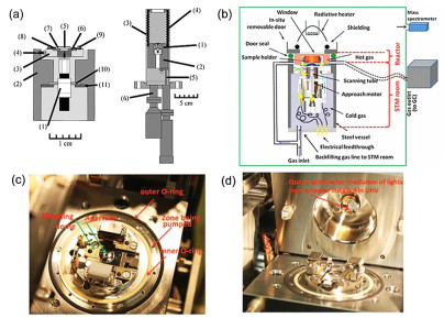
 DownLoad:
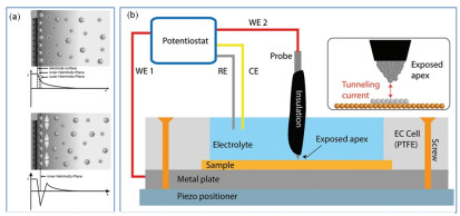
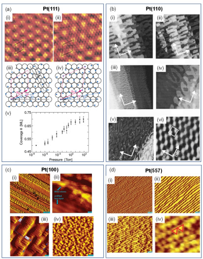
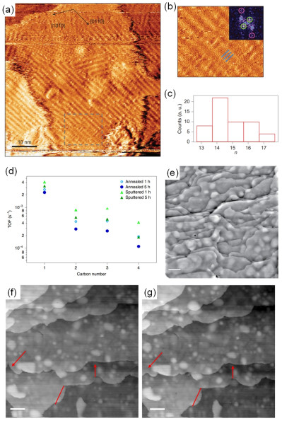
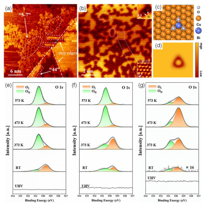
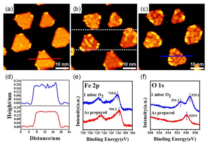
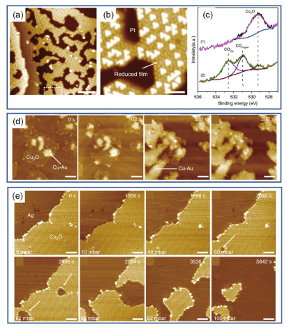
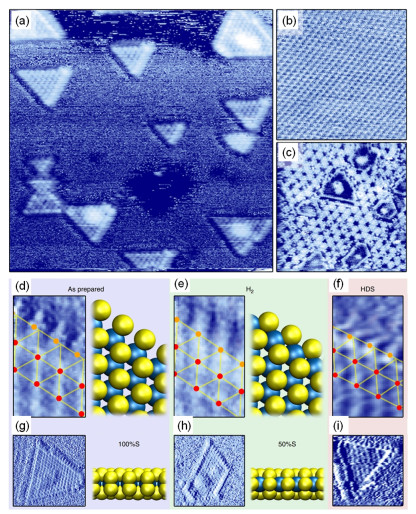
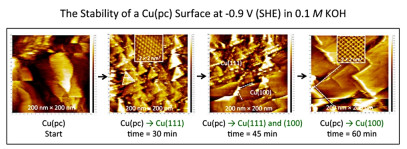
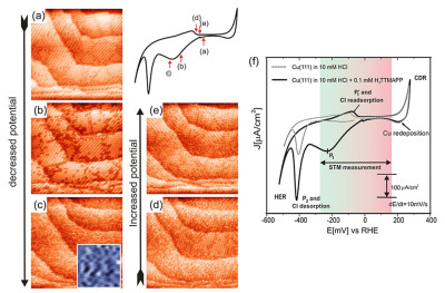
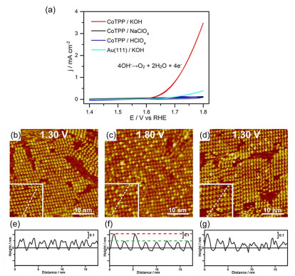
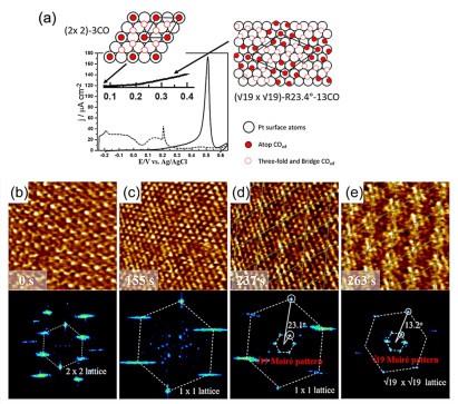
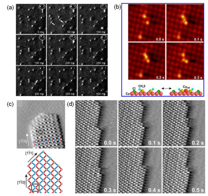
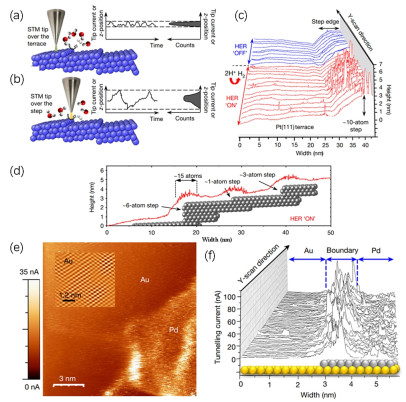

 下载:
下载: