Citation:
Yanmei Gan, Jiajie Zhu, Qixin Zhang, Chaoying Wang, Lunhui Guan, Yi Zhao. Boosting Stable and Fast Potassium Storage of Iron Sulfide through Rational Yolk-Shell Design and Ni Doping[J]. Chinese Journal of Structural Chemistry,
2022, 41(5): 220503.
doi:
10.14102/j.cnki.0254-5861.2022-0044
Boosting Stable and Fast Potassium Storage of Iron Sulfide through Rational Yolk-Shell Design and Ni Doping
College of Chemistry, Fuzhou University, Fuzhou 350108, China
2.
Straits Institute of Flexible Electronics (SIFE, Future Technologies), Fujian Normal University, Fuzhou 350117, China
3.
CAS Key Laboratory of Design and Assembly of Functional Nanostructures, Fujian Key Laboratory of Nanomaterials, Fujian Institute of Research on the Structure of Matter, Chinese Academy of Sciences, Fuzhou 350108, China
4.
School of Physics Science and Engineering, Tongji University, Shanghai 200092, China
Received Date:
28 February 2022 Accepted Date:
04 April 2022 Available Online:
20 May 2022
Abstract:
Metal sulfides have been regarded as promising anodes for potassium-ion batteries (PIBs) due to their high theoretical capacities, while the performance is limited by their intrinsic poor conductivity and large volume fluctuation during the insertion/extraction of large potassium ion. Herein, the battery performance of iron sulfide anode is significantly enhanced through yolk-shell (Y-S) structure design and nickel doping, aiming to realize good structure stability and superior electron/ion transportation. For potassium storage, as-prepared Y-S Ni-FeS2@C shows excellent cyclic performance and sustains high capacities of 328 mA h g-1 after 100 cycles at 0.2 A g-1 and 226 mA h g-1 after 1000 cycles at 1 A g-1. Especially, it displays a superior rate capacity of 200 mA h g-1 at 20 A g-1, higher than that of Y-S FeS2@C and most as-reported metal sulfide anodes for PIBs. The experimental analysis and theoretical calculation illuminate the effect of Ni-doping on decreasing the particle size of iron sulfide and enhancing the ion/electron transport ability, thus accounting for the exceptional rate capability of Y-S Ni-FeS2@C composite.
Currently, lithium-ion batteries (LIBs) have been widely applied in energy storage products particularly portable electronics and hybrid electric vehicles, as they possess long service life and high energy density. However, limited by extreme scarcity and uneven distribution of lithium resources on earth, LIBs show the restriction in wholesale energy storage applications.[1-3] Recently, sodium-ion batteries (SIBs) and potassium-ion batteries (PIBs) have drawn more and more attention as ideal substitutes for LIBs, due to the similarities of physical and chemical properties as well as the abundant sodium/potassium resources and low cost.[4-7] In comparison to SIBs, PIBs profit from their relatively lower standard reduction potential of potassium (-2.93 V vs. SHE) with a higher theoretical energy density. Furthermore, potassium ions show the smallest Stokes radius in some organic solvents among the three alkali metal ions, resulting in the highest conductivity in electrolytes. Nevertheless, the large ionic radius of K+ (1.38 Å) leads to sluggish ion diffusion in solid electrodes and severe structural damage caused by massive volume change during cycles. Therefore, there exists a big challenge to seek appropriate high-performance electrode materials for PIBs.[8-11]
In terms of anode materials, transition metal sulfides such as FeS2, CoS2, SnS2, and so on have been regarded as favorable anodes due to their high theoretical capacities, acceptable redox reversibility, and low cost.[12-14] However, transition metal sulfides also suffer from poor electrical conductivity and serious structural damage owing to the volume expansion/extraction during cycles. To solve these problems, hybridization metal sulfide with carbon nanomaterials under rational microstructure design has been considered as an efficient approach.[15-19] Especially, yolk-shell (Y-S) structure, from which active materials are confined within hollow coating layer with sufficient internal void room, can effectively enhance the conductivity and tolerate the volume variation with enhanced battery performance.[20-23] The Y-S structures can be fabricated through hard/soft-template, self-template, as well as combined methods.[24] For instance, Yao et al. developed a Y-S NiSx@C nanosheet through acid etching method, delivering good cyclic behavior with a high potassium storage capacity of 300 mA h g-1 after 300 cycles at 0.1 A g-1.[25] However, due to the limited contact points between yolk and shell as well as the large particle size of yolk, traditional Y-S structure usually exhibits insufficient ion/electron transportation channels and long diffusion path, thus hampering the rate capability and cycling performance.[26] Besides, it is widespread that heteroatom doping can boost the intrinsic ionic/electronic transport kinetics by modulating the crystal structure and bandgap of electrode materials.[27-30] For example, Fang et al. provided an ion-exchange method to prepare a hierarchical Cu-doped CoSe2 micro-box and exhibited good rate capability of 185 mA h g-1 at 3 A g-1 for SIBs.[31] Nevertheless, the doping strategy alone was unable to effectively accommodate the volume changes of metal sulfide and displayed poor structure stability. Therefore, the rational combination of heteroatom doping and Y-S structure holds great promise to realize high-performance anode materials for PIBs.
Herein, we presented a superior anode material through the rational Y-S structure design and nickel doping of iron sulfide. In the as-obtained Y-S structure, multiple Ni-doped FeS2 nanoparticles (NPs) were encapsulated within hollow carbon layer with large internal void room, denoted as Y-S Ni-FeS2@C composite. This composite was synthesized to inherit the structure merits of Ni-doping for fast electron/ion transport and Y-S structure for good cyclic stability. As an anode for PIBs, it can achieve high capacity (328 mA h g-1 at 0.2 A g-1) and impressive rate capability (200 mA h g-1 at 20 A g-1). Furthermore, it is capable of delivering long-term cycling life and maintaining a capacity of 226 mA h g-1 at 1 A g-1 after 1000 cycles. Moreover, the effect of Y-S structure and Ni-doping on the battery performance has been investigated through the structure characterization, kinetics analysis, theoretical calculation, and ex-situ experiments.
RESULTS AND DISCUSSION
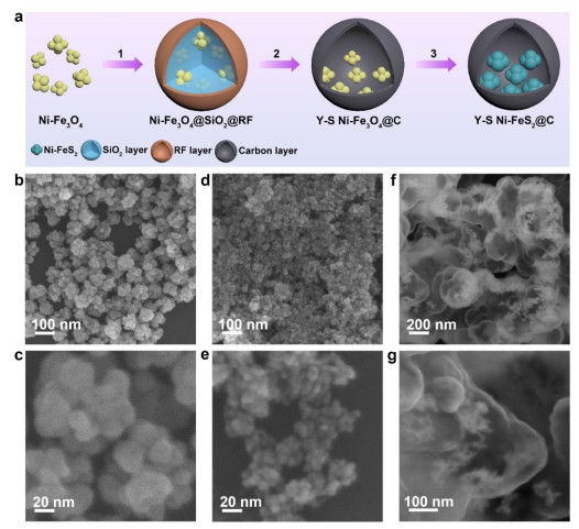
Figure 1a displays the fabrication procedure of Y-S Ni-FeS2@C composite through a classic hard-template method. Firstly, Ni-doped Fe3O4 NPs was synthesized through a solvothermal method and used as precursor.[32] Secondly, Ni-Fe3O4 was subsequently coated with silica layer and resorcinol formaldehyde (RF) layer. Then, Ni-Fe3O4@SiO2@RF composite was carbonized at 450 ℃ in Ar and etched with 2 M NaOH solution.[22] Finally, as-produced Y-S Ni-Fe3O4@C was mixed with sulfur powder and annealed at 500 ℃ to obtain Y-S Ni-FeS2@C. Figure 1b-c display the sphere morphology of pure Fe3O4 particles (~90 nm), which has a porous surface and consists of small primary NPs with the size around 20-30 nm. For Ni-doped Fe3O4, tiny NPs (~10 nm) were aggregated to form an irregular morphology with size around 30-50 nm (Figure 1d-e). After covering with SiO2 and RF, the particles glued together and exhibited the sphere-like shape in Figure S1. The Y-S structure of Ni-Fe3O4@C composite is disclosed in Figure 1f-g, from which the inner Ni-Fe3O4 NPs have no morphology change after the carbonization and base-etching.
Figure 1
Figure 1.
(a) Schematic illustration for the synthesis process of Y-S Ni-FeS2@C composite: 1) covering Ni-Fe3O4 NPs with SiO2 and RF layers, 2) carbonization and NaOH etching to obtain Y-S Ni-Fe3O4@C, 3) sulfuration treatment to produce Y-S Ni-FeS2@C. SEM images of (b-c) Fe3O4, (d-e) Ni-Fe3O4, and (f-g) Y-S Ni-Fe3O4@C composites.
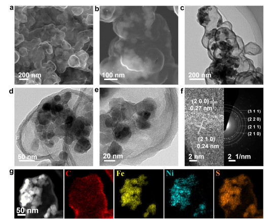
Figure 2 shows the SEM and TEM characterizations of Y-S Ni-FeS2@C composite. As can be seen, multiple Ni-FeS2 NPs were dispersed inside hollow carbon layers with sufficient internal void room. The TEM image in Figure 2d-e further reveals that the particle size of Ni-FeS2 is 25-35 nm, and the thickness of carbon shell is around 15 nm. Figure 2f exhibits the high-resolution TEM (HRTEM) image, disclosing the clear interplanar distances of 0.27 and 0.24 nm for (200) and (210) planes of FeS2. Besides, the welldefined rings in selected-area electron diffraction (SAED) pattern were assigned to the (210), (211), (220), and (311) planes of FeS2. Figure 2g shows the elemental mapping of the Y-S Ni-FeS2@C composite, disclosing that Ni element was homogeneously doped in FeS2 matrix, and the Ni-FeS2 NPs were fully encapsulated within sulfur-doped hollow carbon. The energy dispersive X-ray spectrometry (EDS) image in Figure S2 illustrates that the atomic ratio of Ni and Fe is about 1:5.68, consistent with the 15% Ni-doping of raw material added.
Figure 2
Figure 2.
(a-b) SEM, (c-e) TEM, (f) HRTEM and SAED pattern, (g) STEM image and elemental mapping of Y-S Ni-FeS2@C composite.
As comparison, Y-S FeS2@C without Ni doping was also fabricated by using pure Fe3O4 as precursor. Figure S3 manifests its similar Y-S structure with large FeS2 NPs located within hollow carbon layers. The particle sizes of iron sulfide in Y-S Ni-FeS2@C and Y-S FeS2@C were measured based on the TEM images. As shown in Figure S4, the diameters of Ni-FeS2 particles were mainly distributed at 20-30 nm, while the particle size of FeS2 is mainly concentrated at 40-70 nm. Thus, it can be concluded that Ni-doping can not only decrease the particle size of iron sulfide, but also increase the connection points between Ni-FeS2 and carbon shell, thus benefiting for the superior electron/ion tran sport kinetics. Besides, FeS2 and Ni-FeS2 samples were fabricated by sulfuration treatment of Fe3O4 and Ni-Fe3O4, respectively. Both of them exhibited particle growth during vulcanization process and showed large particle size in Figure S5.
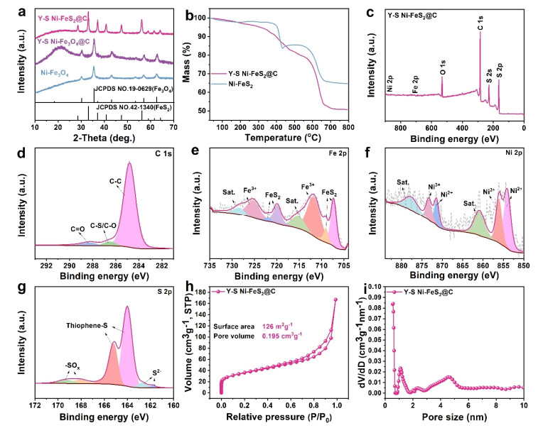
X-ray diffraction (XRD) was conducted to explore the structure evolution during fabrication process. Seen from Figure 3a and Figure S6a, all the Fe3O4, Ni-Fe3O4, Y-S Fe3O4@C, and Y-S Ni-Fe3O4@C composite presented the characteristic peaks indexed to cubic Fe3O4 (JCPDS No. 19-0629). Ni-doped samples exhibited lower and broader diffraction peaks than the undoped samples, consistent with the small particle size of Ni-Fe3O4. The XRD patterns of Y-S FeS2@C and Y-S Ni-FeS2@C were well ascribed to the pyrite FeS2 (JCPDS No. 42-1340), manifesting the successful transformation from iron oxide to iron sulfide after sulfuration treatment. There were no diffraction peaks of carbon layer due to its amorphous structure. Figure 3b and Figure S6b exhibit the TGA curves of as-produced composites in Air atmosphere. Based on the different weight loss between iron sulfide and Y-S structure, the mass ratio of FeS2 and Ni-FeS2 in Y-S structured composites can be calculated to be 78.4 and 78.9 wt%, respectively.
Figure 3
Figure 3.
(a) XRD patterns of Ni-Fe3O4, Y-S Ni-Fe3O4@C, and Y-S Ni-FeS2@C composites. (b) TGA curves of Ni-FeS2 and Y-S Ni-FeS2@C. (c) Survey XPS spectrum, and high-resolution (d) C 1s, (e) Fe 2p, (f) Ni 2p, (g) S 2p XPS spectra of Y-S Ni-FeS2@C. (h) N2 adsorption-desorption isotherm, and (i) pore size distribution of Y-S Ni-FeS2@C.
Figure 3c exhibits the X-ray photoelectron spectroscopy (XPS) spectrum of Y-S Ni-FeS2@C composite, from which strong peaks of C, O, S elements and weak peaks of Fe and Ni were detected. For C 1s spectrum (Figure 3d), it was divided into three peaks at 248.8, 286.5, and 288.2 eV, assigning to C-C, C-O/C-S, and C=O, respectively.[33] According to the NIST XPS Database, the Fe 2p spectrum represented two pairs of peaks at binding energies of 707.3/719.9 and 709.0/721.8 eV, which were assigned to FeS2 marcasite (Figure 3e). The appearance of other two peaks at 711.7 and 725.2 eV along with two satellite peaks at 715.0 and 728.0 eV could be ascribed to Fe3+, which were derived from the oxidation of FeS2 to form Fe2O3.[34-35] As for Ni 2p spectrum (Figure 3f), it contained characteristic peaks of 854.0 and 871.4 eV for Ni2+, and 856.0 and 873.2 eV for Ni3+, accompanying with the satellite peaks at 860.8 and 876.5 eV.[36] As for the S 2p spectrum, the two dominant peaks at 163.7 and 164.9 eV can be ascribed to the thiophene-S in carbon layer (Figure 3g). Besides, the two peaks at 168.1 and 169.3 eV were related to -SOx and the other two weak peaks at low binding energy were resulted from the S2- of Ni-FeS2.[22] In Figure S7, similar Fe, C, and S spectra were detected in Y-S FeS2@C, while no Ni element was observed in the survey curve. Figure 3h displays the nitrogen adsorption-desorption isotherm curves of Y-S Ni-FeS2@C composite. It showed a surface area of 126 m2 g-1, and a pore volume of 0.195 cm3 g-1. The related pore size distribution in Figure 3i, obtained through absorption isotherm by Quench Solid Density Function Theory (QSDFT) method, centered on micropores of 0.6 nm and 1.4 nm as well as mesopores of 4 nm. The Y-S FeS2@C composite presented similar porosity properties in Figure S6c-d. Such abundant porosity can provide enough space room to tolerate the volume changes of iron sulfide without fracture of carbon layer, thus benefiting for the excellent structural stability during cycles.[37]
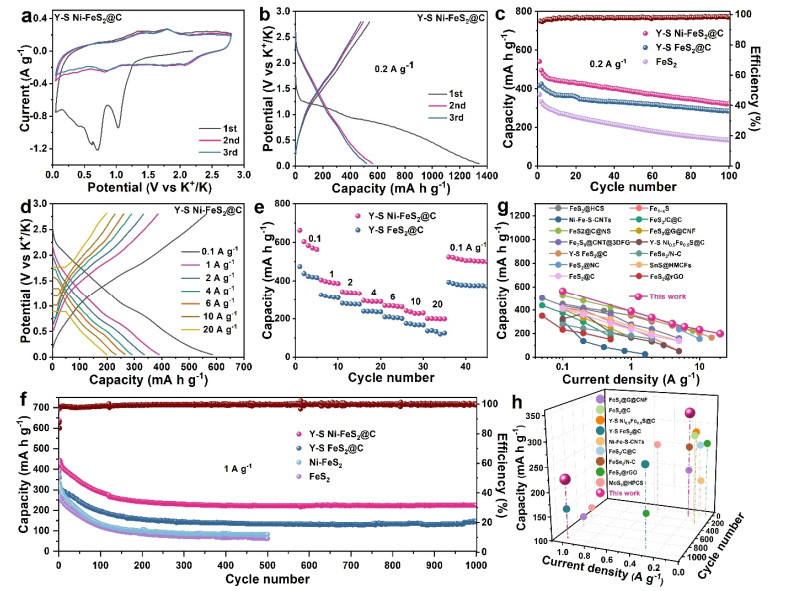
Figure 4a displays the cyclic voltammetry (CV) curves of Y-S Ni-FeS2@C electrode at 0.2 mV s-1. In the initial cathodic scan, the sharp peak around 1.0 V was ascribed to the potassium intercalation to generate K-rich phase (KxNi-FeS2). The broad peaks around 0.7 and 0.4 V were related to the generation of solid electrolyte interface (SEI) layer and further conversion process to form metallic Ni and Fe.[38] In the anodic scan, the peaks around 1.3, 1.8, and 2.5 V were assigned to the reverse conversion reaction from metal to KxNi-FeS2 and the further depotassiation process from K-rich compound.[39] The fine overlapping of the following scans implied its excellent cyclic stability. To further reveal the reaction mechanism of Y-S Ni-FeS2@C during K+ storage, ex-situ XRD was carried out. In Figure S8, at the initial discharge state of 1.0 V, the characteristic peaks of Ni-FeS2 became much weaker than the original state and small peaks of KFeS2 were observed. When discharged to 0.5 V, the diffraction peaks of Ni-FeS2 were totally converted into K-rich phases of KFeS2 and K9Fe2S7, as well as Fe metal. At the stage of 0.05 V, there are no obvious diffraction peaks probably due to the small particle size and weak crystallinity of discharged products. During the charging process at 1.5 and 2.0 V, the diffraction peaks of KFeS2 were reappeared with weak intensity. When fully charged to 2.8 V, the Ni-FeS2 phase was reformed, implying the excellent reaction reversibility of Ni-FeS2 during potassiation/depotassiation process.
Figure 4
Figure 4.
Electrochemical performance of as-prepared composites for PIBs. (a) CV profiles at 0.2 mV s-1 and (b) discharge/charge curves at 0.2 A g-1 of Y-S Ni-FeS2@C electrode for the initial 3 cycles. (c) Cycling performance of FeS2, Y-S FeS2@C, and Y-S Ni-FeS2@C electrodes at 0.2 A g-1. (d) Discharge/charge profiles of Y-S Ni-FeS2@C under diverse current densities. (e) Rate capability of Y-S FeS2@C and Y-S Ni-FeS2@C electrodes from 0.1 to 20 A g-1. (f) Long-term cycling stability of FeS2, Ni-FeS2, Y-S FeS2@C, and Y-S Ni-FeS2@C at 1 A g-1. Comparison of (g) rate capacities and (h) cyclic performance between Y-S Ni-FeS2@C and as-reported anodes for PIBs.
In Figure 4b, the initial discharge/charge profiles of Y-S Ni-FeS2@C electrode at 0.2 A g-1 exhibited capacities of 1343 and 541 mA h g-1. Such capacity loss was due to the formation of SEI layer and the incomplete conversion reaction during cycles. Figure S9 shows the initial charge capacities of 417 and 370 mA h g-1 for Y-S FeS2@C and FeS2, respectively. This result illuminated that the Ni-doping in Y-S structure can effectively enhance the potassium storage capability. Figure 4c displays the cycling performance of FeS2, Y-S FeS2, and Y-S Ni-FeS2@C electrodes at 0.2 A g-1. As can be seen, pure FeS2 electrode showed severe capacity fading and only kept a low capacity of 138 mA h g-1 after 100 cycles. The Y-S structure can greatly enhance the cyclic behavior due to its good structure stability. Thus, Y-S structured Ni-FeS2@C and FeS2@C electrodes maintained high capacities of 328 and 282 mA h g-1 after 100 cycles at 0.2 A g-1.
Figure 4d shows the discharge/charge curves of Y-S Ni-FeS2@C at different current densities, which presented similar shape and exhibited lower overpotentials than Y-S FeS2@C at various rates (Figure S10). In Figure 4e, Y-S Ni-FeS2@C manifested superior rate capacities to Y-S FeS2@C. It delivered high capacities of 390, 336, 284, 258, 232, and 200 mA h g-1 at 1, 2, 4, 6, 10, and 20 A g-1, respectively. When back to 0.1 A g-1, the capacity of Y-S Ni-FeS2@C can return to a high value of 542 mA h g-1. While Y-S FeS2@C only showed low capacities of 168 and 126 mA h g-1 at 10 and 20 A g-1. Moreover, the superb long-term cycling behavior was further illuminated in Figure 4f and Figure S11. As can be seen, the Y-S Ni-FeS2@C electrode presented the highest capacity and best capacity retention among these electrodes at 1 A g-1. After being cycled at 0.1 A g-1 in the first two cycles, the Y-S Ni-FeS2@C showed initial charge capacity of 442 mA h g-1 at 1 A g-1 and sustained a capacity of 226 mA h g-1 after 1000 cycles, much higher than the values of 133 mA h g-1 after 1000 cycle for Y-S FeS2@C and 63 mA h g-1 after 500 cycles for FeS2. Besides, Ni-FeS2 electrode also showed fast capacity decay and sustained a capacity of 83 mA h g-1 after 500 cycles. As compared in Figure 4g-h and Table S1, our Ni-doping Y-S structure enabled remarkable rate capability and long-term cycling stability, which was one of the best results among so far reported anodes for PIBs.
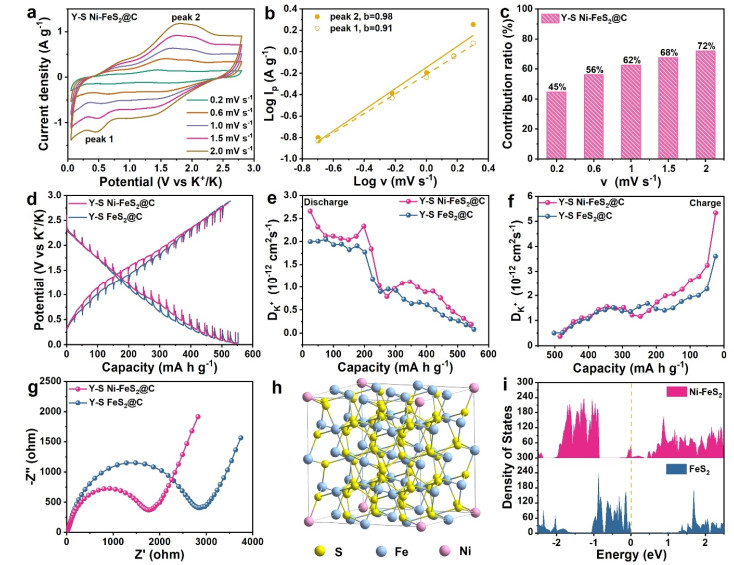
To illustrate the origin of remarkable performance of Ni-doped Y-S structure, CV tests under various rates were performed to evaluate the potassium storage kinetics in Figure 5a. For untangling the K+ storage mechanism, the following equation was introduced: $ {i}_{p}=a{v}^{b} $, where a and b are adjustable parameters, ip is the peak current, and v is the scan rate.[40-42] The b value of approximate 1.0 signifies a typical capacitive-controlled process. As determined in Figure 5b, the b values of Y-S Ni-FeS2@C electrode at peaks 1 and 2 are 0.91 and 0.98, manifesting the storage process of this electrode was dominated by pseudocapacitive behavior. Moreover, here is the equation for further calculating the specific contribution ratio of the capacitive behavior: $ i={k}_{1}v+{k}_{2}{v}^{\frac{1}{2}} $, from which $ {k}_{1}v $ and $ {k}_{2}{v}^{\frac{1}{2}} $ represent diffusion and capacitive behaviors.[38] In Figure 5c, the capacitive contribution of Y-S Ni-FeS2@C electrode gradually enlarged from 45% at 0.2 mV s-1 to 72% at 2.0 mV s-1. Such high capacitive behavior could be derived from the large surface area and small Ni-FeS2 particle, thus leading to excellent rate performance of Y-S Ni-FeS2@C composite.
Figure 5
Figure 5.
(a) CV profiles from 0.2 to 2.0 mV s-1, (b) plots for b-value determination, and (c) capacitive contribution ratio of Y-S Ni-FeS2@C electrode. (d) GITT profiles, the corresponding K+ diffusion coefficients during (e) discharge and (f) charge process, and (g) EIS profiles after 10 cycles of Y-S FeS2@C and Y-S Ni-FeS2@C electrodes. (h) Crystal structure of Ni-FeS2, and (i) DOS for FeS2 and Ni-FeS2.
The charge transfer kinetics was further evaluated by galvanos-tatic intermittent titration technique (GITT), electrochemical impedance spectroscopy (EIS), and density functional theory (DFT) calculation. Figure 5d compares the GITT curve of Y-S Ni-FeS2@C and Y-S FeS2@C anodes, which were recorded by conducting a series of current pulses (50 mA g-1) for 0.5 h followed by relaxation intervals of 2 h. As calculated with the equation based on Fick's second law, the K+ diffusion coefficients ($ {D}_{{K}^{+}} $) of Y-S Ni-FeS2@C were apparently higher than that of Y-S FeS2@C during discharge and charge processes in Figure 5e-f.[43] Additionally, the diffusion resistance was examined by EIS curves after 10 cycles. As shown in Figure 5g, the Ni-doping strategy resulted in a small semicircle diameter in the high-medium frequency region, indicating the high electrical conductivity and low ion diffusion impedance of Y-S Ni-FeS2@C during cycles.[44] Moreover, the density of states (DOS) calculation was conducted to analyze the electrical conductivity of pure FeS2 and Ni-doped FeS2. Figure 5h-i exhibit the crystal structure of Ni-FeS2 and the DOS result. The computational model in Figure 5h consists of 2x2x2 unit cells containing 32 Fe and 64 atoms. One Fe atom is replaced by a Ni atom to investigate doping effect, leading to the Ni/Fe ratio to be 3%. As expected, the FeS2 is a semiconductor, while Ni doping leads to the increase of DOS for FeS2 and endows Ni-FeS2 with metallic conductivity.[29] The Ni atom creates some occupied states close to the conduction band minimum for low concentration, which improves conductivity of the electrode. The effect will be enhanced for high concentration due to more extra electrons.
Lastly, the structure evolution of Y-S Ni-FeS2@C after 100 cycles was observed by ex-situ SEM in Figure S12. It can be seen that the Y-S morphology was preserved intact by the outer carbon shell and internal void space during repeated potassiation/depo-tassiation processes. Therefore, the excellent electrochemical performance of Y-S Ni-FeS2@C electrode can be attributed to the below factors. Firstly, the Y-S structure can provide enough internal void space for tolerating the volume change, and outer carbon layer for hampering its agglomeration to guarantee good structure integrity during cycles. Secondly, the small size of Ni-FeS2 and large surface area of Y-S structure were beneficial for the high surface capacitance contribution. Thirdly, Ni-doping can decrease the particle size of iron sulfide, increase the connect points between yolk and shell, and improve the intrinsic ion/electron transfer ability for boosting the rate capability. Therefore, Y-S Ni-FeS2@C composite can present high capacity, good cyclic performance, and remarkable rate capability as an anode for PIBs.
The excellent performance of Y-S Ni-FeS2@C electrode prompts us to conduct in-depth research on the performance of potassium ion full cells. The cathode was made by mixing thermally annealed perylene-3, 4, 9, 10-tetracarboxylic acid dianhydride (PTCDA), super P carbon black, and carboxymethyl cellulose (8:1:1 in weight) with H2O, which was then coated on Al foil. The PTCDA cathode and the Y-S Ni-FeS2@C anode were precycled in half-cells for five cycles. Then the full cells were assembled with 3 M KFSI in DME as the electrolyte. The voltage range for full cells was 0.5-3.0 V. The specific capacity mentioned in the manuscript was calculated based on the whole mass of Y-S Ni-FeS2@C composite. The performance of Y-S Ni-FeS2 @C// PTCDA full cells is shown in Figure S13. When tested at 0.2 A g-1, the full cell delivers good reversible capacity of 123 mA h g-1 after 150 cycles. And the rate capacities of the full cell are 245.6, 204.8, 149.8, 113.2, 104.3 and 82 mA h g-1 from 0.1 to 2.0 A g-1. The above result implied that Y-S Ni-FeS2@C could be used as a promising anode in full PIB cell for large-scale applications.
CONCLUSION
In summary, the battery performance of iron sulfide has been greatly improved through the combination of Y-S structure design and Ni-doping. As-prepared Y-S Ni-FeS2@C enabled good structure integrity and superior charge transfer kinetics, thus leading to stable and fast potassium storage behavior. As a PIB anode, it can display high capacities of 328 mA h g-1 after 100 cycles at 0.2 A g-1 and 226 mA h g-1 after 1000 cycles at 1 A g-1. Remarkably, a high-rate capacity of 200 mA h g-1 can be reached at 20 A g-1, surpassing the Y-S structure without Ni-doping and most of the metal sulfide anodes for PIBs. Moreover, such combined strategy, aiming to improve both the structure stability and charge transfer ability, provides a new avenue to realize high-performance anode materials for PIBs.
ACKNOWLEDGEMENTS:
This work was supported by the Science and Technology Planning Project of Fujian Province (2021J01151), CAS Key Laboratory of Design and Assembly of Functional Nanostructures (2013DP173231), the Award Program for Fujian Minjiang Scholar Professorship (2021), and the Start-up Funding from FJNU.
COMPETING INTERESTS
The authors declare no competing interests.
Supplementary information is available for this paper at http://manu30.magtech.com.cn/jghx/EN/10.14102/j.cnki.0254-5861.2022-0044 For submission:https://mc03.manuscriptcentral.com/cjsc ADDITIONAL INFORMATION
[1]
Armand, M.; Tarascon, J. M. Building better batteries. Nature2008, 451, 652-657. doi: 10.1038/451652a
[2]
Zeng, X. Q.; Li, M.; Abd El-Hady, D.; Alshitari, W.; Al-Bogami, A. S.; Lu, J.; Amine, K. Commercialization of lithium battery technologies for electric vehicles. Adv. Energy Mater.2019, 9, 1900161.
[3]
Li, M.; Lu, J.; Chen, Z. W.; Amine, K. 30 years of lithium-ion batteries. Adv. Mater.2018, 30, 1800561. doi: 10.1002/adma.201800561
[4]
Chen, M.; Wang, E.; Liu, Q.; Guo, X.; Chen, W.; Chou, S. L.; Dou, S. X. Recent progress on iron- and manganese-based anodes for sodiumion and potassium-ion batteries. Energy Storage Mater.2019, 19, 163-179. doi: 10.1016/j.ensm.2019.03.030
[5]
Liu, Y.; Yang, C.; Zhang, Q.; Liu, M. Recent progress in the design of metal sulfides as anode materials for sodium ion batteries. Energy Storage Mater.2019, 22, 66-96. doi: 10.1016/j.ensm.2019.01.001
[6]
Hosaka, T.; Kubota, K.; Hameed, A. S.; Komaba, S. Research development on K-ion batteries. Chem. Rev.2020, 120, 6358-6466.
[7]
Cao, J.; Xie, Y.; Yang, Y.; Wang, X.; Li, W.; Zhang, Q.; Ma, S.; Cheng, S.; Lu, B. Achieving uniform Li plating/stripping at ultrahigh currents and capacities by optimizing 3D nucleation sites and Li2Se-enriched SEI. Adv. Sci.2022, 202104689.
[8]
Dhir, S.; Wheeler, S.; Capone, I.; Pasta, M. Outlook on K-ion batteries. Chem.2020, 6, 2442-2460. doi: 10.1016/j.chempr.2020.08.012
[9]
Zhang, W. C.; Yiu, L.; Guo, Z. P. Approaching high-performance potassium-ion batteries via advanced design strategies and engineering. Sci. Adv.2019, 5, 7412. doi: 10.1126/sciadv.aav7412
[10]
Kim, H.; Kim, J. C.; Bianchini, M.; Seo, D. H.; Rodriguez-Garcia, J.; Ceder, G. Recent progress and perspective in electrode materials for Kion batteries. Adv. Energy Mater.2017, 8, 1702384.
[11]
Chen, M.; Zhao, J. M.; Sun, C. F. High-volumetric-capacity WSe2 anode for potassium-ion batteries. Chin.J. Struct. Chem.2021, 40, 926-932.
[12]
Pan, Q.; Tong, Z.; Su, Y.; Qin, S.; Tang, Y. Energy storage mechanism, challenge and design strategies of metal sulfides for rechargeable sodium/potassium-ion batteries. Adv. Funct. Mater.2021, 31, 2103912. doi: 10.1002/adfm.202103912
[13]
Wu, Y. H.; Zhang, C. L.; Zhao, H. P.; Lei, Y. Recent advances in ferromagnetic metal sulfides and selenides as anodes for sodium- and potassium-ion batteries. J. Mater. Chem. A2021, 15, 9506-9534.
[14]
Chen, J. W.; Chua, D. H. C.; Lee, P. S. The advances of metal sulfides and in situ characterization methods beyond Li ion batteries: sodium, potassium, and aluminum ion batteries. Small Methods2020, 4, 1900648. doi: 10.1002/smtd.201900648
[15]
Zhao, Y.; Wang, L. P.; Sougrati, M. T.; Feng, Z.; Leconte, Y.; Fisher, A.; Srinivasan, M.; Xu, Z. A review on design strategies for carbon based metal oxides and sulfides nanocomposites for high performance Li and Na ion battery anodes. Adv. Energy Mater.2017, 7, 1601424. doi: 10.1002/aenm.201601424
[16]
Xie, Y.; Cao, J.; Wang, X.; Li, W.; Deng, L.; Ma, S.; Zhang, H.; Guan, C.; Huang, W. MOF-derived bifunctional Co0. 85Se nanoparticles embedded in N-doped carbon nanosheet arrays as efficient sulfur hosts for lithium-sulfur batteries. Nano Lett. 2021, 21, 8579-8586. doi: 10.1021/acs.nanolett.1c02037
[17]
Geng, H. Y.; Peng, Y.; Qu, L. T.; Zhang, H. J.; Wu, M. H. Structure design and composition engineering of carbon-based nanomaterials for lithium energy storage. Adv. Energy Mater.2020, 10, 1903030. doi: 10.1002/aenm.201903030
[18]
Yang, X.; Wang, Z. D.; Fu, Y. R.; Liu, Q.; Xiao, G. Ca2Nb2O7 as a novel open-framework anode material for potassium-ion batteries. Chin.J. Struct. Chem.2021, 40, 233-238.
[19]
Wang, C. Y.; Yao, Q. Q.; Gan, Y. M.; Zhang, Q. X.; Guan, L. H.; Zhao, Y. Monodispersed SWNTs assembled coating layer as an alternative to graphene with enhanced alkali-ion storage performance. Chin.J. Struct. Chem.2022, 41, 2201040-2201046.
[20]
Wu, C.; Tong, X.; Ai, Y. F.; Liu, D. S.; Yu, P.; Wu, J.; Wang, Z. M. M. A review: enhanced anodes of Li/Na-ion batteries based on yolk-shell structured nanomaterials. Nano-Micro Lett.2018, 10, 40. doi: 10.1007/s40820-018-0194-4
[21]
Shi, X. L.; Gan, Y. M.; Zhang, Q. X.; Wang, C. Y.; Zhao, Y.; Guan, L. H.; Huang, W. A partial sulfuration strategy derived multi-yolk-shell structure for ultra-stable K/Na/Li-ion storage. Adv. Mater.2021, 33, 2100837.
[22]
Zhao, Y.; Shi, X. L.; Ong, S. J. H.; Yao, Q. Q.; Chen, B.; Hou, K.; Liu, C.; Xu, Z. J.; Guan, L. H. Enhancing the charge transportation ability of yolk-shell structure for high-rate sodium and potassium storage. ACS Nano2020, 14, 4463-4474.
[23]
Liu, S.; Li, X. Z.; Huang, B.; Yang, J. W.; Chen, Q. Q.; Li, Y. W.; Xiao, S. H. Controllable construction of yolk-shell Sn-Co@void@C and its advantages in Na-ion storage. Rare Metals2021, 40, 2392.
[24]
Lin, L. S.; Song, J.; Yang, H. H.; Chen, X. Yolk-shell nanostructures: design, synthesis, and biomedical applications. Adv. Mater.2018, 30, 1704639. doi: 10.1002/adma.201704639
[25]
Yao, Q. Q.; Zhang, J. S.; Li, J. X.; Huang, W. J.; Hou, K.; Zhao, Y.; Guan, L. H. Yolk-shell NiSx@C nanosheets as K-ion battery anodes with high rate capability and ultralong cycle life. J. Mater. Chem. A2019, 32, 18932.
[26]
Yang, F. H.; Gao, H.; Hao, J. N.; Zhang, S. L.; Li, P.; Liu, Y. Q.; Chen, J.; Guo, Z. P. Yolk-shell structured FeP@C nanoboxes as advanced anode materials for rechargeable lithium‐/potassium-ion batteries. Adv. Funct. Mater.2019, 29, 1808291.
[27]
Li, Y.; Chen, M. H.; Liu, B.; Zhang, Y.; Liang, X. Q.; Xia, X. H. Heteroatom doping: an effective way to boost sodium ion storage. Adv. Energy Mater.2020, 10, 2000927.
[28]
Chen, B.; Chao, D. L.; Liu, E. Z.; Jaroniec, M.; Zhao, N. Q.; Qiao, S. Z. Transition metal dichalcogenides for alkali metal ion batteries: engineering strategies at the atomic level. Energy Environ. Sci.2020, 13, 1096-1131.
[29]
Tan, Z.; Sharma, L.; Kakkar, R.; Meng, T.; Jiang, Y.; Cao, M. H. Arousing the reactive Fe sites in pyrite (FeS2) via integration of electronic structure reconfiguration and in situ electrochemical topotactic transformation for highly efficient oxygen evolution reaction. Inorg. Chem.2019, 58, 7615-7627.
[30]
Li, J.; Liu, Q.; Zhang, Y.; Jiang, J.; Wu, H. B.; Yu, X. Y. Copper and carbon-incorporated yolk-shelled FeP spheres with enhanced sodium storage properties. Chem. Eng. J.2021, 421, 127776.
[31]
Fang, Y.; Yu, X. Y.; Lou, X. W. D. Formation of hierarchical Cu-doped CoSe2 microboxes via sequential ion exchange for high-performance sodium-ion batteries. Adv. Mater.2018, 21, 1706668. doi: 10.1002/adma.201706668
[32]
Xuan, S. H.; Wang, F.; Wang, Y. X. J.; Yu, J. C.; Leung, K. C. F. Facile synthesis of size-controllable monodispersed ferrite nanospheres. J. Mater. Chem.2010, 20, 5086-5094.
[33]
Yao, Q. Q.; Gan, Y. M.; Ma, Z. J.; Qian, X. Y.; Cai, S. Z.; Zhao, Y.; Guan, L. H.; Huang, W. Approaching superior potassium storage of carbonaceous anode through a combined strategy of carbon hybridization and sulfur doping. Energy Environ. Mater.2021, DOI: 10.1002/eem2.12217.
[34]
Han, K.; Zhao, W.; Yu, Q.; Liu, Z.; Li, P.; Wang, W.; Song, L.; An, F.; Cao, P.; Qu, X. Marcasite-FeS2@carbon nanodots anchored on 3D celllike graphenic matrix for high-rate and ultrastable potassium ion storage. J. Power Sources2020, 469, 228429.
[35]
Luo, Y.; Tao, M.; Deng, J.; Zhan, R.; Guo, B.; Ma, Q.; Aslam, M. K.; Qi, Y.; Xu, M. Nanocubes composed of FeS2@C nanoparticles as advanced anode materials for K-ion storage. Inorg. Chem. Front.2020, 7, 394-401.
[36]
Salvati, L.; Makovsky, L. E.; Stencel, J. M.; Brown, F. R.; Hercules, D. M. Surface spectroscopic study of tungsten-alumina catalysts using X-ray photoelectron, ion scattering, and Raman spectroscopies. J. Phys. Chem.1982, 85, 3700-3707.
[37]
Wu, H. F.; Gan, Y. M.; Yao, Q. Q.; Wang, L. P.; Wang, C. Y.; Zhang, Q. X.; Hou, K.; Zhao, Y.; Guan, L. H. Boosting the lithium and sodium storage performance of graphene-based composite via pore engineering and surface protection. Nanotechnology2021, 32, 105402.
[38]
Zhao, Y.; Zhu, J.; Ong, S. J. H.; Yao, Q.; Shi, X.; Hou, K.; Xu, Z. J.; Guan, L. H. High-rate and ultralong cycle-life potassium ion batteries enabled by in situ engineering of yolk-shell FeS2@C structure on graphene matrix. Adv. Energy Mater.2018, 8, 1802565. doi: 10.1002/aenm.201802565
[39]
Yang, S. H.; Park, S. K.; Park, G. D.; Kim, J. H.; Kang, Y. C. Rational synthesis of uniform yolk-shell Ni-Fe bimetallic sulfide nanoflakes@porous carbon nanospheres as advanced anodes for high-performance potassium-/sodium-ion batteries. Chem. Eng. J.2021, 417, 127963.
[40]
Augustyn, V.; Come, J.; Lowe, M. A.; Kim, J. W.; Taberna, P. L.; Tolbert, S. H.; Abruna, H. D.; Simon, P.; Dunn, B. High-rate electrochemical energy storage through Li+ intercalation pseudocapacitance. Nat. Mater.2013, 12, 518-522.
[41]
Kim, H. S.; Cook, J. B.; Lin, H.; Ko, J. S.; Tolbert, S. H.; Ozolins, V.; Dunn, B. Oxygen vacancies enhance pseudocapacitive charge storage properties of MoO3-x. Nat. Mater.2017, 16, 454. https://www.nature.com/articles/nmat4810
[42]
Li, D.; Dai, L.; Ren, X.; Ji, F.; Sun, Q.; Zhang, Y.; Ci, L. Foldable potassium-ion batteries enabled by free-standing and flexible SnS2@C nanofibers. Energy Environ. Sci.2021, 14, 424-436.
[43]
Shen, Z.; Cao, L.; Rahn, C. D.; Wang, C. Y. Least squares galvanostatic intermittent titration technique (LS-GITT) for accurate solid phase diffusivity measurement. J. Electrochem. Soc.2013, 160, A1842-A1846.
[44]
Li, W. D.; Wang, D. Z.; Gong, Z. J.; Yin, Z. M.; Guo, X. S.; Liu, J.; Mao, C. M.; Zhang, Z. H.; Li, G. C. A robust strategy for engineering Fe7S8/C hybrid nanocages reinforced by defect-rich MoS2 nanosheets for superior potassium-ion storage. ACS Nano2020, 14, 16046-16056.
Figure 1
(a) Schematic illustration for the synthesis process of Y-S Ni-FeS2@C composite: 1) covering Ni-Fe3O4 NPs with SiO2 and RF layers, 2) carbonization and NaOH etching to obtain Y-S Ni-Fe3O4@C, 3) sulfuration treatment to produce Y-S Ni-FeS2@C. SEM images of (b-c) Fe3O4, (d-e) Ni-Fe3O4, and (f-g) Y-S Ni-Fe3O4@C composites.
Figure 3
(a) XRD patterns of Ni-Fe3O4, Y-S Ni-Fe3O4@C, and Y-S Ni-FeS2@C composites. (b) TGA curves of Ni-FeS2 and Y-S Ni-FeS2@C. (c) Survey XPS spectrum, and high-resolution (d) C 1s, (e) Fe 2p, (f) Ni 2p, (g) S 2p XPS spectra of Y-S Ni-FeS2@C. (h) N2 adsorption-desorption isotherm, and (i) pore size distribution of Y-S Ni-FeS2@C.
Figure 4
Electrochemical performance of as-prepared composites for PIBs. (a) CV profiles at 0.2 mV s-1 and (b) discharge/charge curves at 0.2 A g-1 of Y-S Ni-FeS2@C electrode for the initial 3 cycles. (c) Cycling performance of FeS2, Y-S FeS2@C, and Y-S Ni-FeS2@C electrodes at 0.2 A g-1. (d) Discharge/charge profiles of Y-S Ni-FeS2@C under diverse current densities. (e) Rate capability of Y-S FeS2@C and Y-S Ni-FeS2@C electrodes from 0.1 to 20 A g-1. (f) Long-term cycling stability of FeS2, Ni-FeS2, Y-S FeS2@C, and Y-S Ni-FeS2@C at 1 A g-1. Comparison of (g) rate capacities and (h) cyclic performance between Y-S Ni-FeS2@C and as-reported anodes for PIBs.
Figure 5
(a) CV profiles from 0.2 to 2.0 mV s-1, (b) plots for b-value determination, and (c) capacitive contribution ratio of Y-S Ni-FeS2@C electrode. (d) GITT profiles, the corresponding K+ diffusion coefficients during (e) discharge and (f) charge process, and (g) EIS profiles after 10 cycles of Y-S FeS2@C and Y-S Ni-FeS2@C electrodes. (h) Crystal structure of Ni-FeS2, and (i) DOS for FeS2 and Ni-FeS2.



 DownLoad:

 下载:
下载: