Scheme 1.
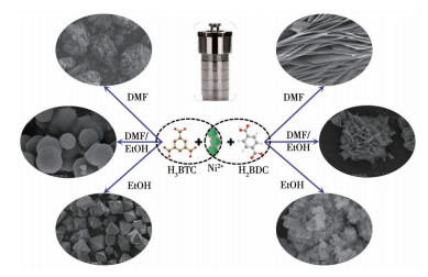
Schematic illustration describing the synthesis of Ni-BTC and Ni-BDC MOFs with various morphologies through a simple solvothermal method with DMF, DMF/EtOH (50:50, V/V), and EtOH as the solvent, respectively
Solvent-Controlled Morphology of Ni-BTC and Ni-BDC Metal-Organic Frameworks for Supercapacitors
Bai-Tong NIU , Wang-Nan XIA , Zhao-Qin LAI , Hong-Xu GUO , Zhang-Xu CHEN

Nowadays, the shortage of nonrenewable energy and increased environmental problems caused by developing the economy have aroused massive researchers devoted to new energy storage devices exploration, particularly rechargeable ion batteries, electrochemical water splitting, and supercapacitors (SCs)[1]. SCs, a novel form of energy storage device between capacitors and batteries, provide the benefits of extended cycle life, rapid charge and discharge, high power density, and minimal environmental impact[2]. As a result, they are widely used in a variety of sectors, such as backup power systems, hybrid electric vehicles, portable electronic equipment, and information technology.
In recent years, metal-organic frameworks (MOFs) have been extensively developed as electrode materials for SCs[3-9]. MOFs are composed of organic linkers and metal ions by strong chemical bonds[10]. Owing to the diverse structure with large specific surface area and rich pore structure, MOFs are hot topics in novel functional materials, and they have aroused more and more concentration among plentiful researchers[11-15]. Nevertheless, a large number of experiments indicate that the electrode materials can reach a high energy density depending not only on the composition but also on the shape and size[16]. Various strategies have been discovered to control the morphologies of MOFs, such as altering the reaction temperature and time[17], tuning the proportion of metal ions[18], and adjusting the pH value[19]. Then, the solvent-controlled morphology of MOFs with uniform shape and adjustable size is a convenient and feasible method to improve their electrochemical performance for supercapacitors[20].
Herein, three kinds of Ni-BTC materials with different shapes and stable configurations were synthesized from the 1, 3, 5-benzenetricarboxylate (BTC3-) ligand, namely, Ni-BTC blocks, nanospheres, and double-pyramid structures. Furthermore, three kinds of Ni-BDC materials with different shapes and stable configurations were synthesized from the 1, 4-benzoate (BDC2-) ligand, namely, Ni-BDC nanosheets, nanoflowers, and block structures. This solvent-adjustment method by changing the solvent is simple and controllable. Experiments revealed that the solvent-controlled morphology of MOFs is a convenient and feasible method to improve the electrochemical performance of supercapacitors.
Unless otherwise specified, all chemical reagents used were of analytical grade and can be used without further purification. 1, 3, 5-benzenetricarboxylic acid (H3BTC) and 1, 4-dicarboxybenzene (H2BDC) were procured from Aladdin Chemistry Co., Ltd (Shanghai, China). Ni(NO3)2·6H2O, ethanol (EtOH), and N, N-dimethylformamide (DMF) were procured from Xilong Chemical Reagent Co. Ltd (China).
The powder X-ray diffraction (XRD) was performed on a Rigaku D/MAX-RB X-ray Diffractometer (Japan) using Cu Kα radiation (λ=0.154 06 nm) at 40 kV and 40 mA, and the XRD patterns were recorded in a 2θ range from 5° to 60°. FT-IR was measured on a NICOLET iS 10IR (USA) Fourier transform infrared spectrometer. The morphologies of the MOFs were characterized on a Hitachi SU8010 field-emission scanning electron microscopy (SEM, Japan) and the operating voltage was 5 kV. A Belsorp-MAX (USA) fully automatic multi-station specific surface, micro, and mesoporous porosity analyzer was used to conduct the nitrogen adsorption-desorption isotherms.
Briefly, the Ni-BTC MOFs were prepared through a simple solvothermal method. For the synthesis of Ni-BTCEtOH, Ni(NO3)2·6H2O (0.436 g, 1.5 mmol) was added to 60 mL of absolute ethanol, followed by the addition of H3BTC (0.294 g, 1.4 mmol). After being stirred for 30 min, the obtained homogeneous solution was transferred into a 100 mL autoclave with a Teflon lining and heated at 180 ℃ for 12 h. After cooling to room temperature, the resultant green precipitate was collected by centrifugation, washed with DMF, ethanol, and deionized water several times, and then dried at 80 ℃ for 12 h. Similarly, Ni-BTCDMF and Ni-BTCDMF/EtOH were synthesized following the same procedures by using DMF and DMF/EtOH (50:50, V/V) as the solvent, respectively.
The Ni-BDC MOFs were prepared through a simple solvothermal method. For the synthesis of Ni-BDCEtOH, Ni(NO3)2·6H2O (0.436 g, 1.5 mmol) was added to 60 mL of absolute ethanol, followed by the addition of H2BDC (0.166 g, 1.0 mmol). The same steps were taken to prepare Ni-BDCEtOH. Similarly, the Ni-BDCDMF and Ni-BDCDMF/EtOH were synthesized following the same procedures by using DMF and DMF/EtOH (50:50, V/V) as the solvent, respectively (Scheme 1).
The production of a working electrode was done utilizing a slurry-forging technique by smearing the sample over the nickel foam (NF, 1 cm×1 cm). In this regard, active material (Ni-BTC or Ni-BDC), polyvinylidene fluoride (PVDF), as well as acetylene black were ground together in a mass ratio of 8:1:1, followed by the addition of ethanol into the powder to create slurry conditions. Subsequently, the slurry was evenly smeared over the NF and dried for 12 h at 60 ℃. Before being used in the electrochemical analysis, the dried NF was subjected to 10 MPa stress testing for about 30 s.
The electrochemical tests were performed at room temperature. The detection of all electrochemical performances was performed on a CS2350H electrochemical workstation (CorrTest Instruments, Wuhan, China).
In the supercapacitor test, the measurements were carried out in a standard three-electrode configuration by utilizing 3 mol·L-1 KOH as the electrolyte, saturated calomel electrode (SCE) as the reference electrode, and platinum wire as the counter electrode. Electrochemical impedance spectroscopy (EIS) measurement was recorded in a range of 105 to 0.01 Hz at open-circuit potential (OCP) by applying a perturbation signal of 10 mV. The specific capacitance of the supercapacitor was obtained by the following equation: Cs=IΔt/(mΔV), where Cs (F·g-1) denotes the specific capacitance, I (A) denotes the discharge current, Δt (s) denotes the discharge time, m (g) denotes the mass of active material, which is weighted separately, and ΔV denotes the potential window.
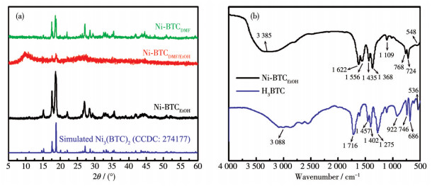
The XRD patterns of Ni-BTCDMF, Ni-BTCDMF/EtOH, Ni-BTCEtOH, and the corresponding simulation, as shown in Fig. 1a. The XRD pattern of Ni-BTCDMF/EtOH had a large and wide characteristic peak at 8.9°, 15.1°, 17.5°, 18.6°, and 27.1°, which confirms that it is an amorphous structure. From the XRD patterns of Ni-BTCDMF and Ni-BTCEtOH, it can be seen that the main sharp peaks at 15.1°, 17.5°, 18.6°, 22.0°, 27.1°, 28.5°, and 35.8°, corresponding to the (202), (213), (301), (421), (315), (511), and (108) crystal planes, respectively, are similar to the standard diffraction pattern of Ni3(BTC)2 (CCDC: 274177) [21]. The FT-IR spectra of Ni-BTCEtOH and H3BTC are illustrated in Fig. 1b to thoroughly examine the as-synthesized Ni-BTCEtOH chemical structure. According to the comparison results, nearly all the FT-IR bands were in close agreement with those of Ni-BTC earlier reported[22]. The typical bands associated with the non-ionized carboxyl groups in BTC3- (i. e., νOH=3 088 cm-1, νC=O=1 716 cm-1, and δC=O=536 cm-1) were not observed in Ni-BTCEtOH[23]. Furthermore, the peaks at 1 622 and 1 556 cm-1 are attributed to the asymmetric stretching vibrations of —COO- coordinated to the Ni2+ ion in a bidentate mode, while the peaks at 1 435 and 1 368 cm-1 are due to symmetric stretching vibrations[24]. Meanwhile, the peaks between 880 and 680 cm-1 indicate that H3BTC is experiencing bending vibrations from the benzene plane[25]. Moreover, the 3 500-3 200 cm-1 band corresponds to hydrogen bond H2O molecules. A stable Ni-BTC structure is formed by fixing scattered Ni active sites via covalent bonds in these chemical structures[26].
The SEM images of three Ni-BTC indicate that they were completely different in morphology and size. When only DMF was used as the solvent, Ni-BTCDMF displayed a block morphology with a particle size of 700-800 μm (Fig. 2a, 2b). After adding EtOH into DMF (50:50, V/V), Ni-BTCDMF/EtOH displayed a spherical morphology with a particle size of 3-5 μm (Fig. 2c, 2d). Besides, the surface of Ni-BTCDMF/EtOH spheres was smooth. Interestingly, when EtOH completely replaced DMF as the solvent, the obtained Ni-BTCEtOH showed a double-pyramid structure (Fig. 2e, 2f) with a particle size of 300-400 μm.
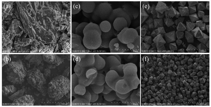
Fig. 3a shows the nitrogen adsorption-desorption isotherms of Ni-BTCDMF, Ni-BTCDMF/EtOH, and Ni-BTCEtOH measured at 77 K. The N2 adsorption-desorption isotherm of Ni-BTC was type Ⅰ (H2) hysteresis loop, which is the principal characteristic of solids with micropores[27-28]. The Brunauer-Emmett-Teller (BET) specific surface areas (SBET) of Ni-BTCDMF, Ni-BTCDMF/EtOH, and Ni-BTCEtOH were determined to be 596, 694, and 736 m2·g-1, respectively. From the pore size distribution curve in Fig. 3b, it can be seen that the pore sizes of Ni-BTCDMF, Ni-BTCDMF/EtOH, and Ni-BTCEtOH were mostly smaller than 5 nm. This indicates that it mainly has two kinds of pore sizes, micropores, and mesopores, which provide a channel for the transport of ions.
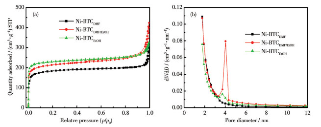
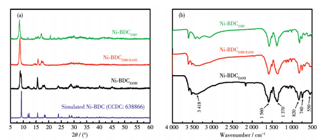
Fig. 4a shows the XRD patterns of Ni-BDCDMF, Ni-BDCDMF/EtOH, and Ni-BDCEtOH, which revealed good correspondence with [Ni3(OH)2(C8H4O4)2(H2O)4] ·2H2O (CCDC: 638866) reported in a previous article[29]. From the XRD patterns of Ni-BDC, it can be seen that the major diffraction peaks were at 9.3°, 11.9°, 12.2°, 15.6°, 18.4°, 18.7°, 23.8°, 28.1°, and 29.3°, corresponding to the (100), (010), (110), (101), (210), (200), (020), (221), and (012) crystal planes, respectively. XRD results show that the synthesized products had a good crystal structure and similar structural characteristics. The FT-IR spectra of Ni-BDCDMF, Ni-BDCDMF/EtOH, and Ni-BDCEtOH are shown in Fig. 4b. The peaks at 550 cm-1 are attributed to O—Ni—O vibrations[30]. The peaks at 820 and 740 cm-1 are characteristic of the paraaromatic C—H stretching bands. The strong bands at 1 560 and 1 370 cm-1 are attributed to the asymmetric and symmetric stretching modes of the coordinated —COO- groups, respectively[31]. Meanwhile, the peaks at 3 418 cm-1 is corresponding to stretching vibrations of the H2O molecules[32]. These results all are in good agreement with the XRD result, and further confirm that the synthesized Ni-BDC MOF is a kind of nickel hydroxyl-terephthalate-based compound[33].
The morphologies of Ni-BDCDMF, Ni-BDCDMF/EtOH, and Ni-BDCEtOH were investigated by SEM. When only DMF was used as the solvent, Ni-BDCDMF displayed a nanosheet morphology with a particle size of 100-150 μm (Fig. 5a, 5b). After adding EtOH into DMF (50:50, V/V), Ni-BDCDMF/EtOH displayed a nanoflowers morphology with a particle size of 50 -80 μm (Fig. 5c, 5d). The flower-like structure was composed of 2D nanosheets assembled by disordered alignment[34]. Interestingly, when EtOH completely replaced DMF as the solvent, the obtained Ni-BDCEtOH showed an irregular bulk structure (Fig. 5e, 5f).
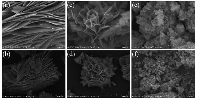
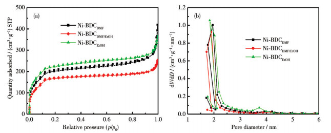
Fig. 6a shows the nitrogen adsorption-desorption isotherms of Ni-BDCDMF, Ni-BDCDMF/EtOH, and Ni-BDCEtOH measured at 77 K. The nitrogen adsorption-desorption isotherm of Ni-BDC is type Ⅱ (H2) hysteresis loop, which is the principal characteristic of solids with micropores. The SBET values of Ni-BDCDMF, Ni-BDCDMF/EtOH, and Ni-BDCEtOH were determined to be 682, 565, and 750 m2·g-1, respectively. From the pore size distribution curves in Fig. 6b, it can be seen that the pore sizes of the samples were in a range of 1.6-2.5 nm, which shows that it has a uniform mesoporosity providing a channel for ion transmission.
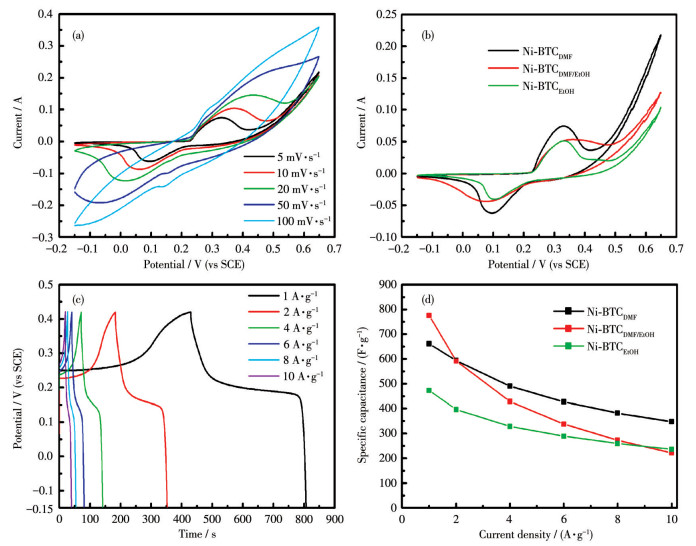
To investigate the electrochemical performance for capacitive energy storage, as-prepared Ni-BTC samples were tested in a three-electrode configuration in a 3 mol·L-1 KOH aqueous electrolyte. The typical cyclic voltammetry (CV) curves of Ni-BTCDMF are shown in Fig. 7a. The CV behavior of Ni-BTC is similar to that of the reported Ni-based MOF material tested in alkaline electrolytes. The charge-storage mechanism may be probably explained by the following redox reactions[35-36]:
|
|
The CV curves of the Ni-BTCDMF, Ni-BTCDMF/EtOH, and Ni-BTCEtOH electrodes at a constant scan rate of 5 mV·s-1 are shown in Fig. 7b. All the electrodes exhibited a nonstandard rectangular shape with obvious redox peaks, suggesting typical pseudocapacitance performance. Fig. 7c shows the galvanostatic charge-discharge (GCD) curves of Ni-BTCDMF composites at current densities of 1, 2, 4, 6, 8, and 10 A·g-1. The specific capacitances were 661.0, 593.7, 490.1, 427.0, 381.8, and 347.4 F·g-1, respectively. The specific capacitances calculated from the discharge curves are plotted in Fig. 7d. The Ni-BTCDMF electrode still retained a high specific capacitance of 347.4 F·g-1 at 10 A·g-1, which was about 52.5% of the value of capacitance at 1 A·g-1, indicating the excellent rate capability.
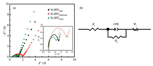
EIS was used to investigate the different materials´ electroconductivity. The circle radius corresponding to Ni-BTCEtOH and Ni-BTCDMF in the high-frequency region was smaller, which means that they have a smaller charge transfer impedance, as illustrated in Fig. 8a (the inset is an enlarged version of the high-frequency region). Table S1 (Supporting information) lists the fitting values of equivalent circuit elements. It is noteworthy that Ni-BTCDMF revealed a lower internal resistance than that of Ni-BTCDMF/EtOH (0.50 Ω) and Ni-BTCEtOH (0.47 Ω) obtained from the intercept of the Nyquist plots with the real axis, manifesting optimized electrode structures and interfacial connections within Ni-BTCEtOH electrode. The corresponding equivalent electrical circuit for the Ni-BTCDMF electrode is displayed in Fig. 8b. In the equivalent circuit, Rs represents the internal resistance (ca. 0.45 Ω), including the solution resistance, the active material (Ni-BDCDMF) intrinsic resistance, and the contact resistance between the active material and the current collector[37]; Rct is the charge transfer resistance (ca. 0.87 Ω), CPE is the constant phase element and Wo is the Warburg resistance[38].
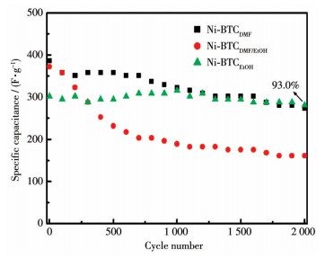
The cycling stability of the Ni-BTCDMF, Ni-BTCDMF/EtOH, and Ni-BTCEtOH electrodes was tested by GCD at 4 A·g-1, as shown in Fig. 9. When the solvent was pure DMF, the specific capacitance of the Ni-BTCDMF electrode decreased from the initial 386.0 to 273.7 F·g-1 after 2 000 cycles, and the capacitance retention rate was 70.9%. The specific capacitance of the Ni-BTCDMF/EtOH electrode decreased from the initial 371.9 to 161.4 F·g-1, and the capacitance retention rate was only 43.4%. This may be related to the changes in the microstructure of the nickel-based MOF during charging and discharging, such as structural collapse. When the solvent was pure EtOH, the specific capacitance of the Ni-BTCEtOH electrode decreased from the initial 301.8 to 280.7 F·g-1, and the capacitance retention rate was 93.0%. Although the specific capacitance of the Ni-BTCEtOH electrode was smaller than that of the Ni-BTCDMF electrode, its cycle performance was better than that of the Ni-BTCDMF electrode.
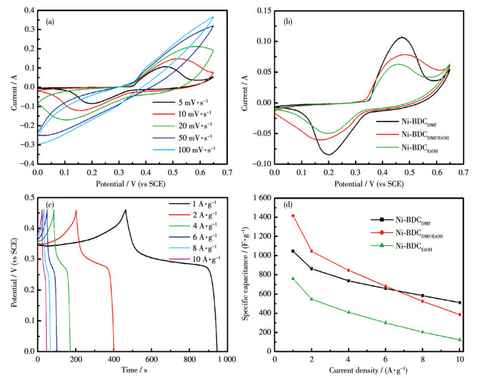
To study the electrochemical property, the CV behaviors of as-prepared MOF electrodes were investigated at different scan rates (5, 10, 20, 50, 100 mV·s-1) in 3 mol·L-1 KOH electrolytes using a three-electrodes test system. Fig. 10a presents the CV curves of the Ni-BDCDMF electrode at different scan rates in a potential range of 0-0.65 V (vs SCE). The CV behavior of Ni-BDC is similar to that of the reported Ni-based MOF material tested in alkaline electrolytes. This process might be represented by the following electron-transfer equation[33, 39]:
|
|
The CV curves of the Ni-BDCDMF, Ni-BDCDMF/EtOH, and Ni-BDCEtOH electrodes at a constant scan rate of 5 mV·s-1 are exhibited in Fig. 10b. A couple of distinct redox peaks were observable, indicating that the typical pseudo-capacitive behavior caused by surface Faradic redox reactions corresponds to the reversible intercalation and deintercalation of OH- ions. Fig. 10c shows the GCD curves of the Ni-BDCDMF electrode within a potential window of 0-0.46 V (vs SCE) at different current densities. The corresponding specific capacitance of the Ni-BDCDMF electrode at 1 A·g-1 was calculated to be 1 044.9 F·g-1. Fig. 10d shows the specific capacitance as a function of discharge current density for the Ni-BDCDMF, Ni-BDCDMF/EtOH, and Ni-BDCEtOH electrodes. The Ni-BDCDMF electrode still retained a high specific capacitance of 509.4 F·g-1 at 10 A·g-1, which was about 48.8% of the capacitance at 1 A·g-1, indicating the excellent rate capability.
The electroconductivity of the Ni-BDCDMF, Ni-BDCDMF/EtOH, and Ni-BDCEtOH electrodes was also investigated by EIS. As shown in Fig. 11 (the bottom inset shows an enlarged version of the high-frequency region), the radius of the circle corresponding to Ni-BDCDMF in the high-frequency region was smaller, which means that it has a smaller charge transfer impedance. The corresponding equivalent electrical circuit is displayed in the top inset of Fig. 11. In the equivalent circuit for Ni-BDCDMF, Rs was ca. 0.36 Ω and Rct was ca. 0.71 Ω (Table S2). At the same time, it also shows that the Ni-BDCDMF electrode is a host material for high electrolyte access, penetration, and ion diffusion, which is conducive to the rapid storage and release of energy and has good electrical conductivity.
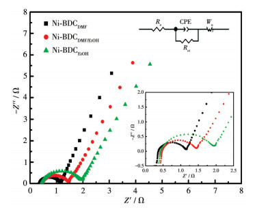
Inset: equivalent electrical circuit for the Ni-BDCDMF electrode (top) and an enlarged version of the high-frequency region (bottom)
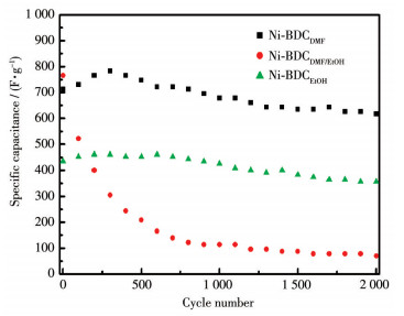
The cycling stability of the Ni-BDCDMF, Ni-BDCDMF/EtOH, and Ni-BDCEtOH electrodes was tested by GCD at 4 A·g-1, as shown in Fig. 12. The specific capacitance of the Ni-BDCDMF electrode decreased from the initial 713.0 to 617.4 F·g-1 after 2 000 cycles, and the capacitance retention rate was 85.9%. The specific capacitance of the Ni-BDCDMF/EtOH electrode decreased from the initial 765.2 to 69.6 F·g-1, and the capacitance retention rate was only 9.1%. It shows that the stability of Ni-BDCDMF/EtOH was very poor, which may be due to the collapse of the structure of Ni-based MOF during charging and discharging. In addition, the FT-IR spectrum after cycling is shown in Fig.S1, which further proves that poor cycling is caused by the structural collapse. The specific capacitance of the Ni-BDCEtOH electrode decreased from the initial 434.8 to 356.5 F·g-1, and the capacitance retention rate was 82.0%.
From the above results and discussion, the solvent has a significant effect on the electrochemical properties of the materials. The possible formation mechanism of Ni-BTCDMF or Ni-BDCDMF can be narrated in terms as follows: DMF and EtOH have different viscosities, saturated vapor pressures, and polarities, which can affect the diffusion rate, supersaturation, nucleation, and crystal growth to some extent[40]. When using DMF alone as the solvent, the deprotonation of H3BTC was fast and produced a crystal aggregate. H2BDC, which was stripped of protons, coordinated with free metal cations (Ni2+). The lamellar MOF structure was formed by confining the growth of the lamellar material to a 2D space because the proton and the metal cation leave simultaneously in the ion domain[34]. Ni-BDCDMF is made up of many-layered micro-sheets, which means that there are thousands of nanochannels in the hierarchical architecture. What is more, thousands of nanochannels might largely improve the diffusion of ions and electrolytes, and the microbundle might offer a stable skeleton for ion intercalation-extraction. In short, the solvent effect leads to different morphologies of the products, which in turn affects the stability of their electrical storage properties. Moreover, the comparison with the reports in the literature is shown in Table 1.
 下载:
导出CSV
下载:
导出CSV
| Material | Specific capacitance/(F·g-1) | Current density/(A·g-1) | Electrolyte | Ref. |
| MOF(V, Ni) | 178 | 1 | 3 mol·L-1 KOH | [41] |
| Pillar Ni-MOF | 552 | 1 | 2 mol·L-1 KOH | [42] |
| Co-MOF | 952.5 | 0.25 | 3 mol·L-1 KOH | [43] |
| Co/Fe-MOF | 319.5 | 1 | 1 mol·L-1 LiOH | [44] |
| Ni/Co-MOF-rGO | 860 | 1 | 6 mol·L-1 KOH | [45] |
| Dandelion-like Ni/Co-MOF | 758 | 1 | 2 mol·L-1 KOH | [46] |
| Ni-BTCDMF | 661.0 | 1 | 3 mol·L-1 KOH | This work |
| Ni-BDCDMF | 1 044.9 | 1 | 3 mol·L-1 KOH | This work |
In conclusion, three kinds of Ni-BTC materials with different shapes and stable configurations were synthesized from the 1, 3, 5-benzenetricarboxylate ligand, namely Ni-BTC blocks, nanospheres, and double-pyramid structures. Furthermore, three kinds of Ni-BDC materials with different shapes and stable configurations were synthesized from the 1, 4-benzoate ligand, namely Ni-BDC nanosheets, nanoflowers, and block structures. This solvent-adjustment method by changing the solvent is simple and controllable. The experimental results reveal that controlling the morphology of MOFs by the solvent is a convenient and feasible method to improve the electrochemical performance of supercapacitors.
Supporting information is available at http://www.wjhxxb.cn
Liang X Q, Chen M H, Zhu H K, Zhu H, Cui X H, Yan J X, Chen Q J, Xia X H, Liu Q. Unveiling the Solid-Solution Charge Storage Mechanism in 1T Vanadium Disulfide Nanoarray Cathodes[J]. J. Mater. Chem. A, 2020, 8: 9068-9076. doi: 10.1039/D0TA02922J
Wang J, Rao M M, Ye C C, Qiu Y C, Su W J, Zheng S R, Fan J, Cai S L, Zhang W G. Cu-MOF Derived Cu-C Nanocomposites towards High Performance Electrochemical Supercapacitors[J]. RSC Adv., 2020, 10: 4621-4629. doi: 10.1039/C9RA09738D
Yang J, Xiong P X, Zheng C, Qiu H Y, Wei M D. Metal-Organic Frameworks: A New Promising Class of Materials for a High Performance Supercapacitor Electrode[J]. J. Mater. Chem. A, 2014, 2: 16640-16644. doi: 10.1039/C4TA04140B
Chen H Y, Huo Y Q, Cai K Z, Teng Y. Controllable Preparation and Capacitance Performance of Bimetal Co/Ni-MOF[J]. Synth. Met., 2021, 276: 116761. doi: 10.1016/j.synthmet.2021.116761
Wang K B, Wang Z K, Liu J D, Li C, Mao F F, Wu H, Zhang Q C. Enhancing the Performance of a Battery-Supercapacitor Hybrid Energy Device through Narrowing the Capacitance Difference between Two Electrodes via the Utilization of 2D MOF-Nanosheetderived Ni@Nitrogen-Doped-Varbon Core-Shell Rings as Both Negative and Positive Electrodes[J]. ACS Appl. Mater. Interfaces, 2020, 12: 47482-47489. doi: 10.1021/acsami.0c12830
Wang K B, Li Q Q, Ren Z J, Li C, Chu Y, Wang Z K, Zhang M D, Wu H, Zhang Q C. 2D Metal-Organic Frameworks (MOFs) for High-Performance Batcap Hybrid Devices[J]. Small, 2020, 16: 2001987. doi: 10.1002/smll.202001987
Wang K B, Wang S R, Liu J D, Guo Y X, Mao F F, Wu H, Zhang Q C. Fe-Based Coordination Polymers as Battery-Type Electrodes in Semisolid-State Battery-Supercapacitor Hybrid Devices[J]. ACS Appl. Mater. Interfaces, 2021, 13: 15315-15323. doi: 10.1021/acsami.1c01339
Guo Y X, Wang K B, Hong Y, Wu H, Zhang Q C. Recent Progress on Pristine Two-Dimensional Metal-Organic Frameworks as Active Components in Supercapacitors[J]. Dalton Trans., 2021, 50: 11331-11346. doi: 10.1039/D1DT01729B
戎红仁, 王先梅, 马艳伟, 高葛祥, 苏豪祺, 赖梨芳, 刘琦. 三维钴基MOF[KCo7(OH)3(ip)6(H2O)4]·12H2O作为超级电容器的高容量电极材料[J]. 无机化学学报, 2021,37,(2): 206-212. RONG H R, WANG X M, MA Y W, GAO G X, SU H Q, LAI L F, LIU Q. Three-Dimensional Cobalt-Based MOF[KCo7(OH)3(ip)6(H2O)4]·12H2O as a High-Capacity Electrode Materials for Supercapacitors[J]. Chinese J. Inorg. Chem., 2021, 37(2): 206-212.
Zhu D D, Qiao M, Liu J L, Tao T, Guo C X. Engineering Pristine 2D Metal-Organic Framework Nanosheets for Electrocatalysis[J]. J. Mater. Chem. A, 2020, 8: 8143-8170. doi: 10.1039/D0TA03138K
Zhang W J, Guo X L, Wang Y X, Zheng Y M, Zhao J J, Xie H, Zhang Z, Zhao Y H. Self-Assembly of Ni-Doped Co-MOF Spherical Shell Electrode for a High-Performance Supercapacitor[J]. Energy Fuels, 2022, 36: 1716-1725. doi: 10.1021/acs.energyfuels.1c03624
Niu B T, Yao B Y, Zhu M H, Guo H X, Ying S M, Chen Z X. Carbon Paste Electrode Modified with Fern Leave-like MIL-47(As) for Electrochemical Simultaneous Detection of Pb(Ⅱ), Cu(Ⅱ) and Hg(Ⅱ)[J]. J. Electroanal. Chem., 2021, 886: 115121. doi: 10.1016/j.jelechem.2021.115121
Wang K B, Guo Y X, Zhang Q C. Metal-Organic Frameworks Constructed from Iron-Series Elements for Supercapacitors[J]. Small Struct., 2021, : 2100115.
戎红仁, 王先梅, 魏英华, 陈晓娟, 赖梨芳, 刘琦. 一种高容量的层状Co-MOF基超级电容器电极材料[J]. 无机化学学报, 2021,37,(12): 2227-2234. doi: 10.11862/CJIC.2021.230RONG H R, WANG X M, WEI Y H, CHEN X J, LAI L F, LIU Q. A Layered Co-MOF Based Electrode Material of Supercapacitor with High-Capacity[J]. Chinese J. Inorg. Chem., 2021, 37(12): 2227-2234. doi: 10.11862/CJIC.2021.230
Niu B T, Zhu M H, Guo H X, Ying S M, Huang X G. Simple Fabrication of a Hexagonal Prisms with Hexagonal Pyramid Tips V2O5@MOF (V, Co) and Its Application as Electrochemical Sensor for Pb2+[J]. Inorg. Chem. Commun., 2021, 133: 108966. doi: 10.1016/j.inoche.2021.108966
Ramachandran R, Zhao C H, Luo D, Wang K, Wang F. MorphologyDependent Electrochemical Properties of Cobalt-Based Metal Organic Frameworks for Supercapacitor Electrode Materials[J]. Electrochim. Acta, 2018, 267: 170-180. doi: 10.1016/j.electacta.2018.02.074
Lee D H, Kim S, Hyun M Y, Hong J Y, Huh S, Kim C, Lee S J. Controlled Growth of Narrowly Dispersed Nanosize Hexagonal MOF Rods from Mn(Ⅲ)-Porphyrin and In(NO3)3 and Their Application in Olefin Oxidation[J]. Chem. Commun., 2012, 48: 5512-5514. doi: 10.1039/c2cc31075a
Sun S Y, Huang M J, Wang P C, Lu M. Controllable Hydrothermal Synthesis of Ni/Co MOF as Hybrid Advanced Electrode Materials for Supercapacitor[J]. J. Electrochem. Soc., 2019, 166(10): A1799-A1805. doi: 10.1149/2.0291910jes
Guo H L, Zhu Y Z, Wang S, Su S Q, Zhou L, Zhang H J. Combining Coordination Modulation with Acid-Base Adjustment for the Control over Size of Metal-Organic Frameworks[J]. Chem. Mater., 2012, 24: 444-450. doi: 10.1021/cm202593h
Sun J, Yu X B, Zhao S H, Chen H M, Tao K, Han L. Solvent-Controlled Morphology of Amino-Functionalized Bimetal Metal-Organic Frameworks for Asymmetric Supercapacitors[J]. Inorg. Chem., 2020, 59: 11385-11395. doi: 10.1021/acs.inorgchem.0c01157
Tan H Y, Liu H Y, Wang C, Wu J. Simple Preparation, Structure and Conductivity of Nickel(Ⅱ) Benzenetricarboxylate Ni3(BTC)2·12H2O[J]. Chin. J. Struct. Chem., 2014, 3: 401-406.
Gan Q M, He H N, Zhao K M, He Z, Liu S. Morphology-Dependent Electrochemical Performance of Ni-1, 3, 5-Benzenetricarboxylate Metal-Organic Frameworks as an Anode Material for Li-Ion Batteries[J]. J. Colloid Interface Sci., 2018, 530: 127-136. doi: 10.1016/j.jcis.2018.06.057
Tan K, Nijem N, Canepa P, Gong Q, Li J, Thonhauser T, Chabal Y J. Stability and Hydrolyzation of Metal Organic Frameworks with Paddle-Wheel SBUs upon Hydration[J]. Chem. Mater., 2012, 24: 3153-3167. doi: 10.1021/cm301427w
Zhu Y X, Zhang Z, Cheng J, Guo H, Yang W J. Ni-BTC Metal-Organic Framework Loaded on MCM-41 to Promote Hydrodeoxygenation and Hydrocracking in Jet Biofuel Production[J]. Int. J. Hydrogen Energy, 2021, 46: 3898-3908. doi: 10.1016/j.ijhydene.2020.10.216
Lei H T, Cao X, Liu X Y, Lei J D. Surfactant-Assisted Synthesis of Zn3(BTC)2 (H3BTC=1, 3, 5-Benzenetricarboxylic Acid) Hollow Nanoparticles[J]. Inorg. Chem. Commun., 2018, 96: 86-89. doi: 10.1016/j.inoche.2018.07.031
Su Y P, Chen C, Zhu X G, Zhang Y, Gong W B, Zhang H M, Zhao H J, Wang G Z. Carbon-Embedded Ni Nanocatalysts Derived from MOFs by a Sacrificial Template Method for Efficient Hydrogenation of Furfural to Tetrahydrofurfuryl Alcohol[J]. Dalton Trans., 2017, 46: 6358-6365. doi: 10.1039/C7DT00628D
Helal A, Naeem M, Arafat M E, Rahman M M. Europium Doped Ni(BTC) Metal-Organic Framework for Detection of Heteroaromatic Compounds in Mixed Aqueous Media[J]. Mater. Res. Bull., 2022, 146: 111604. doi: 10.1016/j.materresbull.2021.111604
Jeong G Y, Singh A K, Kim M G, Gyak K W, Ryu U J, Choi K M, Kim D P. Metal-Organic Framework Patterns and Membranes with Heterogeneous Pores for Flow-Assisted Switchable Separations[J]. Nat. Commun., 2018, 9: 3968. doi: 10.1038/s41467-018-06438-0
Zhang X F, Chang L, Yang Z J, Shi Y N, Long C, Han J Y, Zhang B H, Qiu X Y, Li G D, Tang Z Y. Facile Synthesis of Ultrathin Metal-Organic Framework Nanosheets for Lewis Acid Catalysis[J]. Nano Res., 2019, 12: 437-440. doi: 10.1007/s12274-018-2235-1
Guo H X, Zheng Z S, Zhang Y H, Lin H B, Xu Q B. Highly Selective Detection of Pb2+ by a Nanoscale Ni-Based Metal-Organic Framework Fabricated through One-Pot Hydrothermal Reaction[J]. Sens. Actuators B, 2017, 248: 430-436. doi: 10.1016/j.snb.2017.03.147
Zheng S S, Li B, Tang Y J, Li Q, Xue H G, Pang H. Ultrathin Nanosheet-Assembled[Ni3(OH)2(PTA)2(H2O)4]·2H2O Hierarchical Flowers for High-Performance Electrocatalysis of Glucose Oxidation Reactions[J]. Nanoscale, 2018, 10(27): 13270-13276. doi: 10.1039/C8NR02932F
Xiao Y, Wei W, Zhang M J, Jiao S, Shi Y C, Ding S J. Facile Surface Properties Engineering of High-Quality Graphene: Toward Advanced Ni-MOF Heterostructures for High-Performance Supercapacitor Electrode[J]. ACS Appl. Energy Mater., 2019, 2(3): 2169-2177. doi: 10.1021/acsaem.8b02201
Yan Y, Gu P, Zheng S S, Zheng M B, Pang H, Xue H G. Facile Synthesis of an Accordion-like Ni-MOF Superstructure for High-Performance Flexible Supercapacitors[J]. J. Mater. Chem. A, 2016, 4: 19078-19085. doi: 10.1039/C6TA08331E
Li C, Zheng C M, Jiang H L, Bai S X, Jia J H. Conductive Flowerlike Ni-PTA-Mn as Cathode for Aqueous Zinc-Ion Batteries[J]. J. Alloy. Compd., 2021, 882: 160587. doi: 10.1016/j.jallcom.2021.160587
Zhao S F, Zeng L Z, Cheng G, Yu L, Zeng H Q. Ni/Co-Based Metal-Organic Frameworks as Electrode Material for High Performance Supercapacitors[J]. Chin. Chem. Lett., 2019, 30: 605-609. doi: 10.1016/j.cclet.2018.10.018
Kang L, Sun S X, Kong L B, Lang J W, Luo Y C. Investigating Metal-Organic Framework as a New Pseudo-capacitive Material for Supercapacitors[J]. Chin. Chem. Lett., 2014, 25(6): 957-961. doi: 10.1016/j.cclet.2014.05.032
Liu X X, Shi C D, Zhai C W, Cheng M L, Liu Q, Wang G X. CobaltBased Layered Metal-Organic Framework as an Ultrahigh Capacity Supercapacitor Electrode Material[J]. ACS Appl. Mater. Interfaces, 2016, 8: 4585-4591. doi: 10.1021/acsami.5b10781
Xie Y B, Zhang Y C. Electrochemical Performance of Carbon Paper Supercapacitor Using Sodium Molybdate Gel Polymer Electrolyte and Nickel Molybdate Electrode[J]. J. Solid State Chem., 2019, 23: 1911-1927.
Cao J Z, Yun J H, Zhang N H, Wei Y M, Yang H, Xu Z L. Bifunctional Ag@Ni-MOF for High Performance Supercapacitor and Glucose Sensor[J]. Synth. Met., 2021, 282: 116931. doi: 10.1016/j.synthmet.2021.116931
Wang Z, Dong P, Sun Z X, Sun C, Bu H Y, Han J, Chen S P, Xie G. NH2-Ni-MOF Electrocatalysts with Tunable Size/Morphology for Ultrasensitive C-Reactive Protein Detection via an Aptamer Binding Induced DNA Walker-Antibody Sandwich Assay[J]. J. Mater. Chem. B, 2018, 6: 2426-2431. doi: 10.1039/C8TB00373D
Wu X M, Liu M M, Guo H X, Ying S M, Chen Z X. Polyoxovanadate-Based MOFs Microsphere Constructed from 3-D Discrete Nano-Sheets as Supercapacitor[J]. Chin. J. Struct. Chem., 2021, 40(8): 994-998.
Qu C, Jiao Y, Zhao B, Chen D C, Zou R Q, Walton K S, Liu M L. Nickel-Based Pillared MOFs for High-Performance Supercapacitors: Design, Synthesis and Stability Study[J]. Nano Energy, 2016, 26: 66-73. doi: 10.1016/j.nanoen.2016.04.003
Xuan W L, Ramachandran R, Zhao C H, Wang F. Influence of Synthesis Temperature on Cobalt Metal-Organic Framework (Co-MOF) Formation and Its Electrochemical Performance towards Supercapacitor Electrodes[J]. J. Solid State Electrochem., 2018, 22(12): 3873-3881. doi: 10.1007/s10008-018-4096-7
Yu H N, Xia H C, Zhang J N, He J, Guo S Y, Xu Q. Fabrication of Fe-Doped Co-MOF with Mesoporous Structure for the Optimization of Supercapacitor Performances[J]. Chin. Chem. Lett., 2018, 29: 834-836. doi: 10.1016/j.cclet.2018.04.008
Rahmanifar M S, Hesari H, Noori A, Masoomi M Y, Morsali A, Mousavi M F. A Dual Ni/Co-MOF-Reduced Graphene Oxide Nanocomposite as a High Performance Supercapacitor Electrode Material[J]. Electrochim. Acta, 2018, 275: 76-86. doi: 10.1016/j.electacta.2018.04.130
Gao S W, Sui Y W, Wei F X, Qi J Q, Meng Q K, Ren Y J, He Y Z. Dandelion-like Nickel/Cobalt Metal-Organic Framework Based Electrode Materials for High Performance Supercapacitors[J]. J. Colloid Interface Sci., 2018, 531: 83-90. doi: 10.1016/j.jcis.2018.07.044

Scheme 1 Schematic illustration describing the synthesis of Ni-BTC and Ni-BDC MOFs with various morphologies through a simple solvothermal method with DMF, DMF/EtOH (50:50, V/V), and EtOH as the solvent, respectively

Figure 1 (a) XRD patterns of Ni-BTCDMF, Ni-BTCDMF/EtOH, Ni-BTCEtOH and the corresponding simulation; (b) FT-IR spectra of Ni-BTCEtOH and H3BTC

Figure 2 (a) SEM images of (a, b) Ni-BTCDMF, (c, d) Ni-BTCDMF/EtOH, and (e, f) Ni-BTCEtOH

Figure 3 Nitrogen adsorption-desorption isotherms and (b) pore size distribution curves of Ni-BTCDMF, Ni-BTCDMF/EtOH, and Ni-BTCEtOH

Figure 4 (a) XRD patterns of Ni-BDCDMF, Ni-BDCDMF/EtOH, Ni-BDCEtOH and the corresponding simulation; (b) FT-IR spectra of Ni-BDCDMF, Ni-BDCDMF/EtOH, and Ni-BDCEtOH

Figure 6 (a) Nitrogen adsorption-desorption isotherms and (b) pore size distribution curves of Ni-BDCDMF, Ni-BDCDMF/EtOH, and Ni-BDCEtOH

Figure 7 (a) CV curves of the Ni-BTCDMF electrode at different scan rates; (b) CV curves of as-prepared Ni-BTC electrodes at a scan rate of 5 mV·s-1; (c) GCD curves of the Ni-BTCDMF electrode at different current densities; (d) Specific capacitances of as-prepared Ni-BTC electrodes at different current densities

Figure 8 (a) Nyquist plots of as-prepared Ni-BTC electrodes in 3 mol·L-1 KOH electrolyte; (b) Equivalent electrical circuit for the Ni-BTCDMF electrode

Figure 10 (a) CV curves of the Ni-BDCDMF electrode at different scan rates; (b) CV curves of as-prepared Ni-BDC electrodes at a scan rate of 5 mV·s-1; (c) GCD curves of the Ni-BDCDMF electrode at different current densities; (d) Specific capacitances of as-prepared Ni-BDC electrodes at different current densities

Figure 11 Nyquist plots of as-prepared Ni-BDC electrodes in 3 mol·L-1 KOH electrolyte
Inset: equivalent electrical circuit for the Ni-BDCDMF electrode (top) and an enlarged version of the high-frequency region (bottom)
Table 1. Specific capacitances of some MOF⁃based materials
| Material | Specific capacitance/(F·g-1) | Current density/(A·g-1) | Electrolyte | Ref. |
| MOF(V, Ni) | 178 | 1 | 3 mol·L-1 KOH | [41] |
| Pillar Ni-MOF | 552 | 1 | 2 mol·L-1 KOH | [42] |
| Co-MOF | 952.5 | 0.25 | 3 mol·L-1 KOH | [43] |
| Co/Fe-MOF | 319.5 | 1 | 1 mol·L-1 LiOH | [44] |
| Ni/Co-MOF-rGO | 860 | 1 | 6 mol·L-1 KOH | [45] |
| Dandelion-like Ni/Co-MOF | 758 | 1 | 2 mol·L-1 KOH | [46] |
| Ni-BTCDMF | 661.0 | 1 | 3 mol·L-1 KOH | This work |
| Ni-BDCDMF | 1 044.9 | 1 | 3 mol·L-1 KOH | This work |
 下载: 导出CSV

 扫一扫看文章

扫一扫关注我们