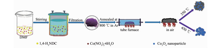
Figure 1.
Diagram of the synthesis of Co3O4/C

Metal-Organic Framework Derived Co3O4/C Composite as High-Performance Anode Material for Lithium-Ion Batteries
Lei GOU , Shao-Pan ZHAO , Peng-Gang LIU , Jiang-Fan YANG , Xiao-Yong FAN , Dong-Lin LI


The global energy crisis and climate change issues have led to a vigorous exploration of electrochemical energy storage systems[1-2]. Lithium-ion batteries (LIBs) have attracted widespread attention due to their unique advantages (e.g., large specific capacity, good chemical stability, high energy density, and no-memory effect)[3-5]. However, currently commercial lithium-ion batteries are approaching the limits of the theoretical capacity prediction of the electrode materials. There-fore, in order to meet the ever-increasing demands of energy, power, safety and stability requirements, it is necessary to develop a new anode material with excellent electrochemical performance[6-9]. Co3O4 has a theoretical capacity of 890 mAh·g-1, which is more than twice that of industrial graphite and is considered to be a promising anode material[10-15]. However, there are still some obstacles to its commercialization, including large volume changes during lithium ions insertion/extraction, which lead to serious electrode pulverization, therefore resulted in a rapid capacity decay, and poor ion and electron conductivity[16]. One effective strategy to solve the above mentioned problems is compositing transition metal oxides with conductive carbon materials, such as graphene[17-18], carbon nanotubes[19-20] and other carbon materials[21-22]. Since carbon can not only improve the conductivity of the electrode material but also function as a buffer to prevent structural collapse caused by large volume changes[23].
In recent years, metal oxides from metal-organic frameworks (MOFs) precursors have received extensive attention[24]. It is well known that MOFs as a kind of hybrid functional materials have potential applications in molecule separation, chemical sensing, hetero-geneous catalysis, drug delivery and gas storage due to their diverse structures, large surface areas and adjustable pore sizes[25-29]. In addition, versatile MOFs structures can be fabricated by changing the metal nodes and organic ligands with coordination hybrid atoms providing a large number of opportunities to obtain various metals, metal oxides, metal sulfurs, metal phosphorous, carbon materials and comp- osites[30-33]. With respect to Co3O4 anode materials synthesized through metal-organic frameworks as precursors′ route, ZIF-67 is one of the commonly used MOFs precursors[34-37]. Shao et al. obtained two hollow structured Co3O4 (ball-in-dodecahedron and concaved-odecahedron) via one-step and two-step calcination of ZIF-67, respectively[38-39]. Qu et al. prepared graphene-supported ultrafine Co3O4 through thermal decomposi-tion of GO/ZIF-67[39]. In addition to ZIF-67, some other MOFs such as Prussian blue analogue Zn3[Co(CN)6]2[40], [Co3(HCOO)6]DMF (DMF = N, N-dimethylformamide)[41], Co-BTC (BTC = 1, 3, 5-benzenetricarboxylate)[42], Co(1, 4-BDC)(DMF) (BDC = 1, 4-benzenedicarboxylate)[43] have also been reported. Due to the different MOFs precursors and different calcination process were used, Co3O4 anodes showed different morphologies and different electrochemical performances.
We have synthesized a Co3O4 anode material by calcination of Co2(NDC)2(DMF)2 (NDC = 1, 4-naphthalene dicarboxylate, DMF = N, N-dimethylformamide) in air, which shows a capacity of 1 058.9 mAh·g-1 after 100 cycles at a current density of 200 mA·g-1 [44]. Consid-ering the ligand that contains a larger conjunctive system than terephthalic acid, which may contribute more carbon content during the carbonization process. Thus, in this work, we synthesized a Co3O4/C composite by a two-step calcination of Co2(NDC)2(DMF)2. Comp-ared with our previously work, this work has significantly improved the battery performance. The resulted Co3O4/C composite exhibited an excellent rate performance with high average discharge specific capacities, which was also superior to most reported cobalt oxides anode materials.
Co2(NDC)2(DMF)2 was synthesized according to literature[44]. Typically, 1, 4-naphthalene dicarboxylic acid (1, 4-H2NDC) (1 mmol, 0.216 g) and Co(NO3)2·6H2O (0.5 mmol, 0.145 g) were dissolved in N, N-dimethylformamide (DMF) (30 mL). The mixture was transferred to and sealed in a 50 mL Teflon-lined stainless steel autoclave after 30 min stirring, kept at 130 ℃ for 48 h, and finally cooled to room temperature. The purple precipitate Co2(NDC)2(DMF)2 was collected by centrifugation and dried at 60 ℃ in an oven for 12 h after rinsing with DMF for three times.
Co3O4/C composite was synthesized by a two-step calcination process that was calcining the Co2(NDC)2(DMF)2 precursor in a tube furnace at a temperature of 800 ℃ for 3 h with a heating rate of 2 ℃·min-1 in argon atmosphere, then at 350 ℃ for an hour in an ambient atmosphere. As for comparison, pure Co3O4 was obtained by calcining Co3O4/C composite under 450 ℃ in air for several hours to remove the carbon component.
The X-ray powder diffraction (XRD) mode of the product was recorded using a Bruker D8 Advance diffractometer with Cu Kα (λ = 0.154 nm) at 40 kV and 40 mA in a scanning range of 5°~70° (2θ). The content of carbon in Co3O4/C composite was determined by thermogravimetric analysis (TGA) was carried out using a TA SDT Q600 thermoanalyser under air flow at 10 ℃·min-1 from room temperature to 800 ℃. The comp-onent was confirmed by X-ray photoelectron spectros-copy (XPS) using an X-ray photoelectron spectrometer (ThermoFisher). Field-emission scanning electron microscope (FE-SEM) images were taken on Zeiss sigma 500 FE-SEM using a 5 kV focus voltage to research the morphologies of the materials. Raman spectrum was obtained using a Laser Raman spectros-copy (in Via, RENISHAW) using a 514 nm argon ion laser.
The electrochemical measurements of all samples were measured by fabricating CR2025 type coin cells in an argon-filled glove box. To prepare a working electrode, the as-synthesized active materials, acetylene black (Super-P) and polyvinylidene fluoride (PVDF) were mixed in N-mzethyl pyrrolidone (NMP) with a weight ratio of 55:35:10 to form a homogeneous slurry. The resulting slurry was pasted onto the surface of a copper foil current collector and dried at 100 ℃ in vacuum oven for 12 h. The coin cells were assembled in an argon filled glove box with the as-prepared materials as the test electrode, metallic lithium as the counter and reference electrode, 1 mol·L-1 LiPF6 in a 1:1 (V/V) mixture of ethylene carbonate (EC) and dimethyl carbonate (DMC) as the electrolyte, and Celgard 2400 micro-porous membrane as the separator. After standing for 24 h, the galvanostatic charge-discharge and rate tests were carried out on a new Neware current test system with a voltage range of 0.01 to 3 V. The cyclic voltammetry (CV) measure-ments were performed at the Versa STAT3 electro-chemical workstation with a measurement range of 0.01 to 3 V and a scan rate of 0.1 mV·s-1. Electro-chemical impedance spectroscopy (EIS) measurements were performed using a Versa STAT3 electrochemical workstation with a frequency range of 100 kHz to 10 mHz and a signal amplitude of 5 mV.
Co2(NDC)2(DMF)2 was used as the precursor to obtain Co3O4/C composite due to a higher carbon content could be obtained after calcination where the naphthalene had a larger conjugated ring than benzene ring. The experimental process was shown as Fig. 1.
The X-ray diffraction (XRD) pattern of Co2(NDC)2(DMF)2 was in good agreement with the literature[44], indicating successful synthesis of the precursor (Fig.S1). After two-step calcination, the purple precursor was converted to a black sample, which was also characterized by XRD analysis. As shown in Fig. 2a, all diffraction peaks of 19°, 31.27°, 36.85°, 38.54°, 44.81°, 55.65°, 59.36°, 65.65°, 68.6°, and 69.73° could be used as the unique index of Co3O4 (PDF No.42-1467). There was no diffraction peak of carbon detected in the XRD pattern, indicating that the decomposed carbon may exist in the form of amorphous state. The existence of amorphous carbon was further confirmed by Raman spectrum due to the strong D band peak (Fig. 2b).
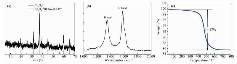
The final residual carbon content was determined by TGA measurement at a heating rate of 10 ℃·min-1 in air, as shown in Fig. 2c. There were two distinct stages of weightlessness. The occurrence of a weight loss of about 0.5% below 200 ℃ could be attributed to the release of the absorbed gases or moisture on the surface of the Co3O4/C composite. Then an abrupt weight loss indicated that amorphous carbon has burned out before the temperature increased to 650 ℃. When the temperature was raised above 650 ℃, the residue content remained constant. Thus, the carbon content in Co3O4/carbon composite was calculated to be 14.47%(w/w).
The surface composition of Co3O4/C was chara-cterized by XPS (Fig. 3). The typical characteristic peaks on the full map are clearly visible (Fig. 3a), the chara-cteristic peaks of 284.43, 530.35, 780.24 eV corres-ponded to the characteristic peaks of C1s, O1s and Co2p, respectively, confirming that C, O, and Co were the main elements in the samples. The existence of C element which was attributed to the residues from the decomposition of organic ligands. The convolutional Co2p spectrum is depicted in Fig. 3b. There were two strong peaks at 779.76 and 794.93 eV, respectively, corresponding to the Co2p3/2 and Co2p1/2 spin-orbital peaks of Co3O4, respectively[45-47]. The energy separation between Co2p3/2 and Co2p1/2 was approximately 15 eV, which was consistent with the standard Co3O4 spectra[46-49]. It can be seen from the spectrum of C1s that the main carbon peak at 284.43 eV belonged to amorphous carbon in Fig. 3c. The peak at 284.7 eV was designated to C-C/C = C contamination, which often led to a significant asymmetry in the graphitized C1s peak towards higher binding energy, which confirmed the presence of carbon to some extent. The peak positions were 286.4 and 290.1 eV, respectively, due to the presence of C-O and O-C = O[46-47, 50-51], indicating the presence of carbon and oxygen-containing functional groups. Fig. 3d showed the de-volume XPS spectrum of the O1s with three different peaks at 533.1 (C-OH), 531.2 (O-C), and 530 eV (O = C-OH)[46-47].
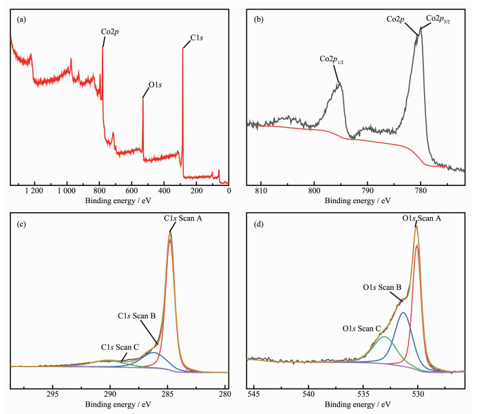
Fig. 4 showed the SEM images of Co3O4/C composite. As can be seen from Fig. 4a, the sample maintained the same block-shaped structure as the precursor (Fig.S2). As shown in Fig. 4b, it can be clearly seen that these micro-sized blocks were not as dense as the precursor, and the surface of the block was not as smooth as the precursor, which formed some cracks. It can be seen from the high magnifica-tion SEM images (Fig. 4c) that the micro-scale blocks were composed of a large number of nanoparticles and tiny void spaces between particles, which is beneficial to the diffusion of the electrolyte. The corresponding elemental mapping shown in Fig. 4d indicated the existence of Co, O and C. We deduced that Co3O4 particles were uniformly dispersed into the carbon network.
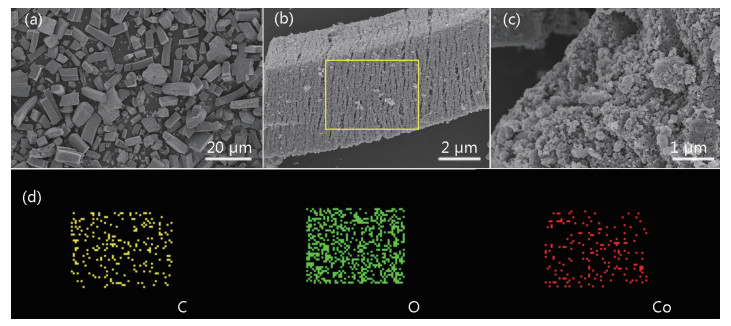
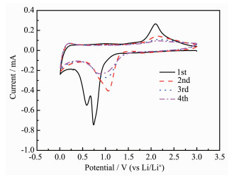
Fig. 5 showed the cyclic voltammogram (CV) of the first three cycles of Co3O4/C at a voltage range of 0.01 to 3 V and a scan rate of 0.1 mV·s-1. In the first cycle, two strong cathodic peaks appeared at 0.6~0.75 V due to the initial reduction of cobalt metal by Co3O4 during discharge. A multi-step electrochemical reduc-tion reaction of Co3O4 with metal Co (Co3O4+8Li++8e- → 4Li2O+3Co)[52-53] formed a partially irreversible solid electrolyte interface (SEI)[53-54]. A broad oxidation peak of about 2.1 V occurred during the charging process due to the oxidation of cobalt into Co3O4 and Li2O decomposition. From the second cycle, the reduction peak moved to about 1.1 V, and the position of the oxidation peak did not deviate too much. This was still the formation of clusters and the formation of Co3O4 phase between the metal Co and Li2O in the conversion reaction[52, 55-56]. In the subsequent cycles, the intensity and voltage position of main cathode and anode peaks showed a good overlap, indicating that the insertion and extraction reactions had good reversibility. The result showed that the electrochemical reversibility of Co3O4/C gradually formed after the initial cycle.
In order to further evaluate the electrochemical performance of the Co3O4/C nanocomposite, a constant current discharge/charge reaction was carried out with a constant current density of 200 mA·g-1 at a potential range of 0.01 to 3.0 V. Fig. 6 showed the charge-discharge curves and compared the cycle performance of Co3O4/C with pure Co3O4. It can be seen from Fig. 6a that the discharge platform of Co3O4/C material appeared at 1.3 and 1.2 V, and the capacity contribu-tion of the 1.2 V platform was large. In addition, the plateau about 2.0 V in charging process could be attributed to the Co3O4 reformation, based on the given conversion reaction of Co3O4+8Li++8e-
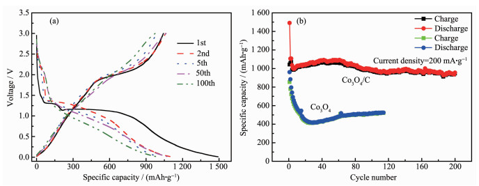
The cycle performances of pure Co3O4 and Co3O4/C composite electrodes at 200 mA·g-1 are shown in Fig. 6b. The initial specific discharge capacity of the Co3O4/C composite electrode was 1 491.4 mAh·g-1, which was still remained at 980 mAh·g-1 after 200 cycles. In contrast, despite the higher initial capacity of the Co3O4, the subsequent capacity dropped down rapidly to a minimum of 457 mAh·g-1 at the 20th cycle. Obviously, under the same experimental condi-tions, the cycle performance of Co3O4/C nanocomposite electrode was significantly better than that of Co3O4. This indicated that carbon played a very important role in providing electronic conductive paths and reducing the stress caused by volume changes, ultimately giving the anode a superior performance.
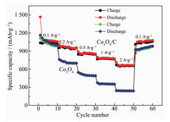
The rate performances of Co3O4/C composite and Co3O4 are shown in Fig. 7. The average discharge capacities of Co3O4/C nanocomposite were 1 076.3, 976.2, 872.9, 783.6 and 670.1 mAh·g-1 at the current densities of 100, 200, 500, 1 000 and 2 000 mA·g-1, respectively. In addition, when the current density switched back to 100 mA·g-1, the capacity value returned to 1 087 mAh·g-1, showing a good stability. In terms of pure Co3O4 electrode, the capacity decayed rapidly as the current density increased. The discharge capacities at 100, 200, 500, 1 000, and 2 000 mA·g-1 were 1 057.3, 743.1, 505.8, 355.7 and 243.2 mAh·g-1, respectively. These results demonstrated that the Co3O4/C composite not only had better cycle perfor-mance, but also had a significantly improved rate performance, which may be due to the important role of carbon played in improving the conductivity and buffering the volume changes during the electrode reaction.
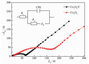
Electrochemical impedance spectroscopy measurements were also conducted for Co3O4/C and Co3O4 electrodes. The Nyquist plots and corresponding fitting curves based on the inset equivalent circuit were given in Fig. 8 and the fitting values were listed in Table S1. In the equivalent circuit, R and R were respectively ohmic resistance (total resistance of the electrolyte, separator and electrical contacts) and charge-transfer resistance[56-57]. CPE was the constant phase angle element, which contained a double layer capacitor, and ZW represented the Warburg impedance reflecting the solid state diffusion of lithium ion into the bulk of the active materials[56-57]. In general, the smaller the diameter of a semicircle, the lower the charge-transfer resistance of the electrode[57-60]. It could be seen that the semicircular radius of Co3O4/C in the high to medium region was significantly smaller than that of pure Co3O4, which was in consistent with the fitting result that a smaller Rct values 28.2 Ω for Co3O4/C than 46.02 Ω for Co3O4, indicating that the charge transfer at the electrode/electrolyte interface was easier, and the reactivity was higher after carbon composting.
In this study, Co3O4/C was fabricated by using Co2(NDC)2(DMF)2 as the precursor through a two-step calcination techniques. It had been found that the Co3O4/C composite delivered a high capacity, good cycling stability and rate capability as compared to pure Co3O4 counterpart when used as anode for LIBs. In particular, Co3O4/C delivered a quite outstanding storage capacity of discharge capacity of 1 000 mAh·g-1 after 200 cycles in a current density of 200 mA·g-1 and 670 mAh·g-1 at a current density of 2 000 mA·g-1. Its good electrochemical performance was attributed to the reasonable choice of organic ligand that provided more carbon in the composite which can efficiently buffer the volume changes of Co3O4 during the Li ion insertion/extraction processes and greatly reduce the charge-transfer resistance.
Acknowledgements: This work was supported by the National Natural Science Foundation of China (Grants No.21103013, 21473014), the Natural Science Foundation of Shanxi Province (Grant No.2016JM5082), Student′s Platform for Innovation and Entrepreneurship Training Program (Grants No.201810710113, 201910710469).
Supporting information is available at http://www.wjhxxb.cn
Sasaki T, Ukyo Y, Novak P. Nat. Mater., 2013,12:569-575 doi: 10.1038/nmat3623
Ji L, Lin Z, Alcoutlabi M, et al. Energy Environ. Sci., 2011,4:2682-2699 doi: 10.1039/c0ee00699h
Aricò AS, Bruce P, Scrosati B, et al. Nat. Mater., 2005,4:366-377 doi: 10.1038/nmat1368
Lan D, Chen Y Y, Chen P, et al. ACS Appl. Mater. Interfaces, 2014,6:11839-11845 doi: 10.1021/am503378n
Wei X J, Gou H, Mo Z L, et al. Ionics, 2016,22:1197-1207 doi: 10.1007/s11581-016-1635-z
Simon P, Gogotsi Y, Dunn B. Science, 2014,343:1210-1211 doi: 10.1126/science.1249625
Lukatskaya M R, Dunn B, Gogotsi Y. Nat. Commun., 2016, 7:12647 doi: 10.1038/ncomms12647
Wang G P, Zhang L, Zhang J J. Chem. Soc. Rev., 2012,41:797-828 doi: 10.1039/C1CS15060J
Mei J, Liao T, Kou L Z, et al. Adv. Mater., 2017,29:1700176 doi: 10.1002/adma.201700176
Tummala R, Guduru R K, Mohanty P S. J. Power Sources, 2012,199:270-277 doi: 10.1016/j.jpowsour.2011.10.048
Tummala R, Guduru R K, Mohanty P S. J. Power Sources, 2012,209:44-51 doi: 10.1016/j.jpowsour.2012.02.071
Marzuki N S, Taib N U, Hassan M F, et al. Electrochim. Acta, 2015,182:452-457 doi: 10.1016/j.electacta.2015.09.119
Wang Y, Zhang H J, Wei J, et al. Energy Environ. Sci., 2011,4:1845-1854 doi: 10.1039/c0ee00802h
Shen L S, Wang C X. Electrochim. Acta, 2014,133:16-22 doi: 10.1016/j.electacta.2014.03.182
Tan Y L, Gao Q M, Yang C X, et al. Sci. Rep., 2015,5:1-11
Reddy M V, Subba Rao G V, Chowdari B V R. Chem. Rev., 2013,113:5364-5457 doi: 10.1021/cr3001884
Lee S H, Sridhar V, Jung J H, et al. ACS. Nano, 2013,7:4242-4251 doi: 10.1021/nn4007253
Lin J, Peng Z W, Xiang C S, et al. ACS. Nano, 2013,7:6001-6006 doi: 10.1021/nn4016899
Eom J Y, Kwon H S. ACS Appl. Mater. Interfaces, 2011,3:1015-1021 doi: 10.1021/am101051v
Lee H J, Yoo J K, Park J H, et al. Adv. Energy Mater., 2012,2:976-982 doi: 10.1002/aenm.201100725
Gómez-Cámer J L, Morales J, Sánchez L. J. Mater. Chem., 2011,21:811-818
Wang G R, Wang L, Zhu F L, et al. Electrochim. Acta, 2017,257:138-145 doi: 10.1016/j.electacta.2017.10.077
Qiu J H, Yu M, Zhang Z H, et al. J. Alloys Compd., 2019, 775:366-371 doi: 10.1016/j.jallcom.2018.10.129
Bala S, Mondal I, Goswami A, et al. J. Mater. Chem. A, 2015,3:20288-20296
Tian B B, Ning G H, Gao Q, et al. ACS Appl. Mater. Interfaces, 2016,8:31067-31075 doi: 10.1021/acsami.6b11772
Stock N, Biswas S. Chem. Rev., 2012,112:933-969 doi: 10.1021/cr200304e
Tan J C, Civalleri B. CrystEngComm, 2015,17:197-198 doi: 10.1039/C4CE90162B
Zhou H C, Kitagawa S. Chem. Rev., 2014,43:5415-5418
Hu H, Zhang J T, Guan B Y, et al. Angew. Chem. Int. Ed., 2016,55:9514-9518 doi: 10.1002/anie.201603852
Jin L N, Zhao X S, Qian X Y, et al. Mater. Lett., 2017,199:176-179 doi: 10.1016/j.matlet.2017.04.016
Wang L, Wu J F, Chen Y Q, et al. Electrochim. Acta, 2015, 186:50-57
Gan Q M, Zhao K M, Liu S Q, et al. Electrochim. Acta, 2017,250:292-301 doi: 10.1016/j.electacta.2017.08.075
Wang F X, Han Q G, Yi Z, et al. J. Electroanal. Chem., 2017,807:196-202 doi: 10.1016/j.jelechem.2017.10.039
Li J B, Yan D, Lu T, et al. Chem. Eng. J., 2017,325:14-24
Yang Q, Feng C Q, Liu J W, et al. Appl. Surf. Sci., 2018, 443:401-406 doi: 10.1016/j.apsusc.2018.02.230
Zhuang G L, Gao Y F, Zhou X, et al. Chem. Eng. J., 2017, 330:1255-1264
Shao J, Wan Z M, Liu H M, et al. Mater. Chem., 2014,2(31):12194-12200 doi: 10.1039/C4TA01966K
Zheng S S, Li X R, Yan B Y, et al. Adv. Energy Mater., 2017,7(18):1602733
Qu Q T, Gao T, Zheng H Y, et al. Carbon, 2015,92:119-125 doi: 10.1016/j.carbon.2015.03.061
Zhu D Q, Zheng F C, Xu S H, et al. Dalton Trans., 2015,44(38):16946-16952 doi: 10.1039/C5DT02271A
Han Y, Zhao M L, Dong L, et al. J. Mater. Chem. A, 2015,3:22542-22546 doi: 10.1039/C5TA06205E
Zhang F, Qi D D, Zhang X G. Int. J. Electrochem. Sci., 2016,11:189-199
Li C, Chen T Q, Xu W J, et al. J. Mater. Chem. A, 2015,3(10):5585-5591
Gou L, Ma L, Zhao M J, et al. J. Mater. Sci., 2019,54:1529-1538
Wu Z S, Ren W, Wen L, et al. ACS Nano., 2010,4:3187-3194 doi: 10.1021/nn100740x
Liu J J, Liu H C, Wang F, et al. RSC Adv., 2015,5(110):90785-90796 doi: 10.1039/C5RA20476C
Li F, Zhai G H, Ren H J, et al. Ionics, 2018,24(1):111-120
Cai T, Huang H, Deng W, et al. Appl Catal. B, 2015,166:393-405
Todorova S, Kolev H, Holgado J P, et al. Appl Catal. B, 2010,94:46-54 doi: 10.1016/j.apcatb.2009.10.019
Dedryvère R, Laruelle S, Grugeon S, et al. Chem. Mater., 2004,16:1056-1061 doi: 10.1021/cm0311269
Biesinger M C, Payne B P, Grosvenor A P, et al. Appl. Surf. Sci., 2011,257:2717-2730 doi: 10.1016/j.apsusc.2010.10.051
Fang D, Li L C, Xu W L, et al. J. Mater. Chem. A, 2013,1:13203-13208 doi: 10.1039/c3ta12310c
Zhuang G L, Gao Y F, Zhou X, et al. Chem. Eng. J., 2017, 330:1255-1264 doi: 10.1016/j.cej.2017.08.076
Li W Y, Xu L N, Chen J. Adv. Funct. Mater., 2005,15:851-857
Zhao Y, Huang Y, Wang Q F, et al. Electron. Mater. Lett., 2013,9:683-686 doi: 10.1007/s13391-012-2182-z
Yang S Z, Cui G L, Pang S P, et al. ChemSusChem, 2010,3:236-239 doi: 10.1002/cssc.200900106
Zhu G, Jiao B J, Li J T. Mater. Res. Innovations, 2014,18(7):528-534 doi: 10.1179/1433075X13Y.0000000197
Slepski P, Darowicki K, Janicka E, et al. J. Solid State Electrochem., 2012,16:3539-3549 doi: 10.1007/s10008-012-1825-1
Park S J, Kim Y J, Lee H. J. Power Sources, 2011,196:5133-5137 doi: 10.1016/j.jpowsour.2011.01.105
Yang Q, Feng C Q, Liu J W, et al. Appl. Surf. Sci., 2018,443:401-406 doi: 10.1016/j.apsusc.2018.02.230

Figure 2 XRD pattern (a), Raman spectrum (b) and TGA curve (c) for the Co3O4/C composite

Figure 3 XPS survey spectra of the Co3O4/C (a), XPS spectra of Co2p (b), XPS spectra of C1s (c) and XPS spectra of O1s (d)

Figure 4 SEM images of Co3O4/C composite at different magnifications (a~c) and corresponding elemental mapping (d)

Figure 5 CV curves of Co3O4/C electrode using a voltage window of 0.01~3 V at rate of 0.1 mV·s-1

Figure 6 (a) Charge-discharge curves of Co3O4/C materials; (b) Cycling performances of Co3O4/C composite and pure Co3O4 electrode at 200 mA·g-1

 扫一扫看文章


扫一扫关注我们
 下载:
下载:

 下载:
下载:

