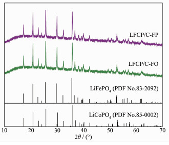
Figure 1.
XRD patterns of LFCP/C samples

Synthesis and Electrochemical Performances of Carbon Coated LiFe0.5Co0.5PO4 Solid Solution as Cathode Materials
Yan-Jun ZHONG , Zhen-Guo WU , Hai TIAN , Xiao-Dong GUO , Ben-He ZHONG , Xin-Long WANG


Lithium-ion batteries (LIBs) that can effectively store energy in the form of chemicals are now attract-ing the international community's concern for applica-tions in portable electronic devices and electrical vehicles[1-2]. Cathode materials which determine the energy density of LIBs at one level have become a hot topic in recent years[3-5]. LiFePO4, as the most famous member of the family of olivine-type lithium transition metal phosphates (LiMPO4, M=Fe, Mn, Co, Ni), is quite attractive for the cathodes of LIBs due to its good stability, low cost, and abundant in nature[6-9]. However, its relatively low potential of 3.45 V (vs Li+/Li, as below) would restrict its further application because of the ever-increasing demand for efficient energy storage systems in hybrid electric vehicles and plugin hybrid electric vehicles. LiCoPO4 also has been attracted much attention for its high working potential (4.8 V) at the stability limit of the carbonate-based liquid electrolytes and its small lattice volume change (~2%) during charge/discharge processes between the CoPO4 and LiCoPO4 compounds[10-12]. Nevertheless, remarkable capacity fading caused by structure deterioration and electrolyte decomposition limit its practical application. Thus, it would be of momentous importance if it can combine the excellent cycling behaviour of LiFePO4 and the high operation voltage of LiCoPO4. In fact, olivine solid solutions especially LiFe1-xMnxPO4 has been investigated intensively in recent years[13-16]. Inspired by this, the binary olivine LiFexCo1-xPO4 com-pounds which are scarcely reported, would be worth studying.
The electrochemical performances of olivine LiMPO4 are usually limited by the poor electronic conductivity and low Li-ion mobility. Various methods have been attempted to improve the battery perfor-mance of lithium iron phosphate. Among them, it is facile and efficient to composite the LiMPO4 with carbon nanomaterials[17-19]. Carbon nanomaterials usually serve as a conductive agent to improve the electrical condu-ctivity while increasing the material porosity in which the solid-state diffusion distances are significantly shortened[20-23]. According to our knowledge, the nano-structure and carbon coating effects about LiFexCo1-xPO4 component seem to have received less attention among the few previous reports[24-26]. Based on the previous reports, the carbon layer is more difficult to be coated on the surface of LiCoPO4 than other olivine-structured compounds like LiFePO4, which may be associated with the distinct surface features of LiCoPO4[27-28]. This could make it more challenging to get a well carbon coated LiFexCo1-xPO4 solid solution composite with full and homogeneous carbon coverage. As demonstrated in previous reports[29-31], it is easily obtain nanomaterials with desired carbon coating via rheological phase method, for it ensures improved quality of mixing and optimized element and particle size distributions. Besides, the heat and mass transfer between the solid particle and fluid can be carried out easily and quickly in the solid-liquid rheological mixture[32-34]. In our previous works[29, 35-37], we successfully used the rheological phase method to synthesize LiMn0.5Fe0.5PO4/C, Li3V2(PO4)3/C, LiFe0.5Mn0.3Co0.2PO4/C composites.
In current study, we have reported the preparation of LiFe0.5Co0.5PO4/C (LFCP/C) composite by a facile rheological phase method and evaluated their electrochemical performances as cathode materials for LIBs. Based on the results from SEM and TEM, it is clearly proved that the LFCP/C sample synthesized via FeC2O4·2H2O exhibits smaller particles size, better dispersion and more favorable carbon coating effect than the one by FePO4·4H2O, thus leading to the more excellent Li-storage capability.
The carbon decorated LiFe0.5Co0.5PO4/C (denoted as LFCP/C) samples were synthesized by rheological phase method. In a typical synthesis for 0.02 mol of LFCP/C product, stoichiometric amount of Li2CO3, FePO4·4H2O or FeC2O4·2H2O, CoCO3 and NH4H2PO4 as raw materials, 2 g of stearic acid as carbon source, and 6 mL of ethylalcohol (AR) as grinding aid were used. After planetary ball milling at 500 r·min-1 for 10 h, the obtained rheological mixture was preheated at 400 ℃ for 5 h and then sintered at 600 ℃ for 10 h in a tube furnace with argon as the shielding gas to yield the LFCP/C product. The LFCP/C composites via FePO4·4H2O and FeC2O4·2H2O are correspondingly labeled as LFCP/C-FP and LFCP/C-FO, respectively.
Powder X-ray diffraction (XRD) measurement was performed on Rigaku Ultima Ⅳ device using Cu Kα radiation (λ=0.154 nm), operating at 35 kV×30 mA in range 2θ from 10° to 70° with the scanning speed of 5°·min-1 for identification of phase as-prepared LFCP/C materials. The particle morphology of the as-prepared compounds was characterized using a field emission scanning electron microscope (FESEM, S-4800) operated 15 kV. Transmission electron microscope (TEM, JEM-2100) operated 200 kV was further used to observe the morphology structure and carbon coating effect of the samples. An automated surface area analyzer (ASAP2020, Micromeritics) based on BET method using nitrogen adsorption-desorption isotherms was employed for specific surface area measurement. The carbon content of the synthesized composite was detected by Vario EL Ⅲ Elemental analyzer (Elementar Analysen Syetem GmbH).
The electrochemical performance was measured using CR2025 coin cells. The positive electrode was fabricated by a mixture of active material, carbon black (CB), and LA-133 (a kind of water-soluble binder purchased from Chengdu Yin Di Le Power Technology Co., Ltd., China) with wactive material: wCB: wLA-133=80: 10: 10 mixed in water solution. The slurry was coated uniformly onto the aluminum foil and dried at 120 ℃ for 12 h in a vacuum oven, and then punched in model and weighed. The coin cells were assembled in an argon-filled glove box using Li metal as the anode and porous polypropylene film (Celgard 2400) as the separator. The employed high-voltage electrolyte mainly consists a solution of 1 mol·L-1 LiPF6 in a solvent mixture of ethylene carbonate (EC) and dimethyl carbonate (DMC) (VEC: VDMC=1: 1). The charge-discharge tests were galvanostatically performed between 2.5 and 5.0 V with various C-rates (1C=150 mA·g-1) on the battery test system (Neware BTS). The electro-chemical impedance spectroscopy (EIS) was measured on a Zahner electrochemical workstation between 10 mHz to 100 kHz with the alternating current voltage (AC) voltage amplitude of 5 mV. All electrochemical tests were carried out at room temperature.
The XRD patterns of the as-prepared LFCP/C samples are presented in Fig. 1. All diffraction chara-cteristic peaks for the two samples are assigned to olivine structure in orthorhombic and Pnma (62) space group based on the standard XRD patterns of LiFePO4 (PDF No.83-2092) and LiCoPO4 (PDF No.85-0002). There are no impurities observed in the patterns, and the peak strength and peak position are very similar for the two samples, implying that high-purity products were obtained by both the Fe raw materials. Besides, good crystallinity can be inferred for the two samples as evidenced from the narrow and sharp peaks. Results based on elemental analyzer indicate that the residual carbon content for LFCP/C-FP and LFCP/C-FO are 2.72% and 1.98% (w/w), respectively, while no carbon peak presented in the XRD patterns because of the relatively low content and the amorphous state.
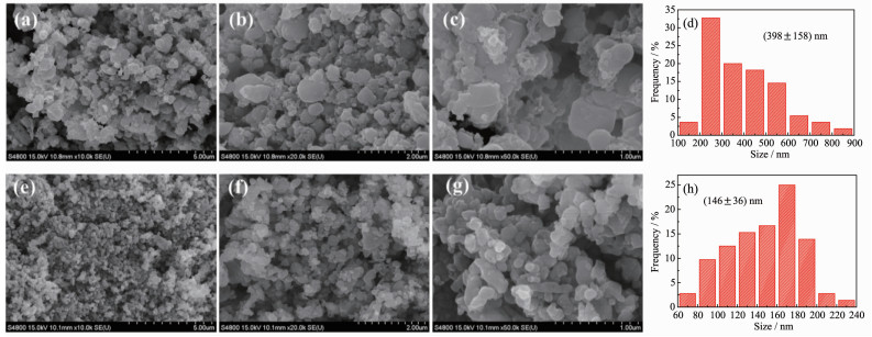
Fig. 2 shows the SEM images for LFCP/C-FO and LFCP/C-FP. As can be clearly observed from low-magnification SEM images in Fig. 2(a, e) which provide an overview of the morphology of the as-prepared products, LFCP/C-FO and LFCP/C-FP are composed of nanoparticles, while the particles seem more serious aggregation in LFCP/C-FP evidenced by some micros-ized aggregate in the image. According to the repre-sentative high-magnification SEM images in Fig. 2(b, c, f, g), both of the samples show nanoparticle morpho-logy but LFCP/C-FO seems more uniform with signifi-cantly smaller average particle size. The statistics of particle size distribution shown in Fig. 2(d, h), which are respectively based on SEM images of Fig. 2(b, f), also verified that LFCP/C-FO possesses a narrower particle size distribution and smaller average particle size of 146 nm than LFCP/C-PO. Furthermore, in the high-magnification SEM image of Fig. 2(c) for LFCP/C-FP, some flocculent carbon is visible scattered by particles, suggesting that some carbon has not been covered on the surface of particles. Unsurprisingly, as characterized by nitrogen adsorption-desorption analy-sis, LFCP/C-FO (44 m2·g-1) has a higher BET specific surface area than LFCP/C-FP (23 m2·g-1), which could mainly be associated with the smaller particle size and higher dispersity for the former. The fundamental cause for the structural feature of LFCP/C-FO may be derived from a lot of gas generated by FeC2O4·2H2O thermal decomposition in the calcination process. In general, a larger specific surface area can effectively increase the interface between electrode and electrolyte, thus enhancing an effective charge transfer across the interface[38].
To further demonstrate the difference in particle morphology and carbon coating effect of the LFCP/C samples, Fig. 3 gives the TEM and HRTEM images. Fig. 3(a) shows the irregular shaped aggregate of LFCP/C-FP composed by nanoparticles with an inho-mogeneous size distribution, and the serious adhesion phenomenon between particles can be observed. The surface of particle seems barely coated by carbon layer, and even some striking quilted carbon is dishe-veled around the particles, as shown in Fig. 3(b). Only a small part of particles has been coated by the carbon layer effectively, such as the one shown in Fig. 3(c), where a ~2.0 nm thickness carbon layer is coated on the outer of particles. The lattice with d-spacing 0.301 nm and reconcilable with the lattice fringe values of (211) plane olivine structure were evident in Fig. 3(c). Fig. 3(d) shows LFCP/C-FO contains well-proportioned spherical or ellipsoidal particles, and the grain diameter is about 50~100 nm being coated by amorphous carbon. No stacked carbon can be observed in Fig. 3(e), implying that the desired carbon coating effect has been realized in the LFCP/C-FO sample. Fig. 3(f) shows that the particle is covered by a ~2.5 nm thickness carbon layer, and there are different lattice spaces of 0.253, and 0.292 nm, corresponding to (131), and (200) atomic layers of LiFe0.5Co0.5PO4, respectively. These indicate that the particle has a well-ordered crystal structure. Previous researches have proven that fine carbon coating can increase the electronic conductivity of materials and buffer the mechanical damage of the active materials during the Li ion insertion/extraction process[39]. With the above analysis, it can be inferred that the LFCP/C-FO may offer better electrochemical performances.
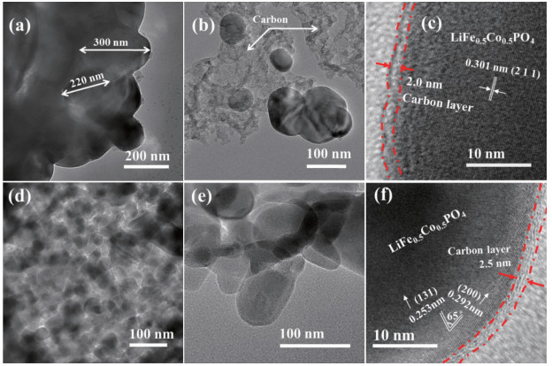
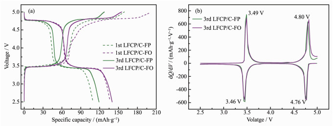
Fig. 4(a) displays galvanostatic charge/discharge voltage profiles at a current density of 0.05C between 2.5 and 5.0 V of the first and third cycles for the two cathode materials. The profiles present two reversible voltage plateaus around 3.5 and 4.8 V for the two LFCP/C samples, corresponding to the Fe3+/Fe2+ and Co3+/Co2+ redox, respectively. The first cycle charge and discharge profiles of LFCP/C-FP deliver specific capacities of 159.8 and 109.6 mAh·g-1, respectively, with coulombic efficiency of 68.6%. As a comparison, LFCP/C-FO exhibits higher charge capacity of 201.3 mAh·g-1 and discharge capacity of 136.1 mAh·g-1, with coulombic efficiency of 67.6%. The capacity loss more than 30% in the initial cycle for the both elec-trodes is mainly attributed to the electrolyte decom-position and irreversible reaction associated to Co2+/Co3+, which is commonly observed for high-voltage materials like LiCoPO4[40-41]. Then in the third cycle, the discharge capacity increased to 119.2 mAh·g-1 for LFCP/C-FP and 139.9 mAh·g-1 for LFCP/C-FO. In addition, the coulombic efficiency reaches a value of more than 90% at the 3rd cycle for both electrodes. Furthermore, as can be observed that from the charge/discharge voltage profiles, the platform length of near 4.8 V for LFCP/C-FP is somewhat shorter than that of LFCP/C-FO while the one of ~3.4 V is similar, signifying that the lower capacity for LFCP/C-FP ought to be mainly ascribed to Co3+/Co2+ redox reaction. This phenomenon could be associated with electro-chemical activation process of LFCP/C electrodes. Fig. 4(b) shows the differential capacity profiles of the 3rd cycle for the samples. There are two cathodic/anodic peaks positioned at about 3.49/3.46 V and 4.80/4.76 V identified as Fe3+/Fe2+ and Co3+/Co2+ redox couple, respectively, in accordance with the charge/discharge profiles.
Rate performances of the two electrodes at different rates are shown in Fig. 5(a). A relatively higher discharge capacity was found for LFCP/C-FO than LFCP/C-FP at various discharge rates. Specifically, the LFCP/C-FO electrode delivers a reversible capacity of 137.5, 129.5, 114.1, 100.0, 86.7, 73.9 and 57.6 mAh·g-1 at 0.1C, 0.2C, 0.5C, 1C, 3C, 5C and 10C respectively. As a comparison, the corresponding capacity for LFCP/C-FP is 115.8, 105.5, 92.7, 85.5, 72.0, 61.3 and 42.2 mAh·g-1, respectively. When the current rate is set back to 0.1C after rate perfor-mances measurement, the capacity for LFCP/C-FO and LFCP/C-FP is 120.2 and 111.2 mAh·g-1, respectively.
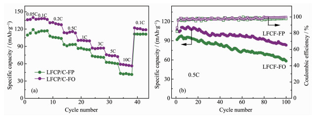
Fig. 5(b) gives the comparison of cycling perfor-mance at 0.5C in the range of 2.5~5.0 V for the two LFCP/C electrodes. During the cycling process, the coulombic efficiency gradually increases and then steadily reaches a value higher than 98.0%, indicating the good reversibility of as-obtained LFCP/C samples. Remarkably, LFCP/C-FO shows slower capacity fading than the other one. It maintains 83.1 mAh·g-1 after 100 cycles with 78.1% of capacity retention ratio, in contrast, only discharge capacity of 58.3 mAh·g-1 and capacity retention ratio of 63.5% for LFCP-FP. These results demonstrate that LFCP/C-FO has more excellent electrochemical performance, which can be associated with the smaller particle size which shortens the diffusion distance Li+, and the uniform and full carbon coating layer which not only enhance the electronic conductivity, but also act as a protective barrier for active materials from being severely corroded.
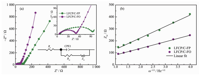
EIS tests were conducted to disclose the reasons for the better comprehensive electrochemical perfor-mances of LFCP/C-FO. Before the EIS tests, the cells were first charged and discharged for three cycles at 0.1C. Subsequently, the EIS tests were taken at the full discharge state of 2.5 V. Fig. 6(a) gives the Nyquist plots for LFCP/C-FP and LFCP/C-FO. The small interrupt is corresponding to the solution impedance (Re). The semicircle can be assigned to the charge transfer impedance (Rct) in the high to medium frequ-ency. The short quasi-straight line observed in the low frequency is related to the solid-state diffusion of Li+ in the active materials, which is also called Warburg impedance (Zw). The Nyquist plots are fitted by using an equivalent circuit as inserted in Fig. 6(a). A constant phase element (CPE) is placed to represent the double layer capacitance and passivation film capacitance[42]. The calculated values of Re and Rct for LFCP/C-FP and LFCP/C-FO are listed in the Table 1. It seems that the Re value of LFCP/C-FO (5.83 Ω) is similar to that of LFCP/C-FP (6.17 Ω). The main difference between these two electrodes is the charge transfer resistant (Rct). The value of Rct for LFCP/C-FO (48.75 Ω) is much lower than that of LFCP/C-FP (110.9 Ω), which can be attributed to the uniform and full carbon coating layer in the surfaces of primary particles. It reveals that on one side, the higher specific surface area is beneficial for the electrolyte to thoroughly contact with the particle surface, which will facilitate the Li+ to travel from the electrolyte to the solid material. On the other side, there are still connected points between the primary particles (due to the formation of the secondary particles), resulting in a facile transfer of Li+ and the electron in the solid active material[17, 43]. Thus, it is also one of the main reasons for the improved rate capability of LFCP/C-FO. The lithium ion diffusion coefficient can be calculated according the following equations[44-45]:
|
$ D = \left( {{R^2}{T^2}} \right)/\left( {2{A^2}{n^4}{F^4}{C^2}{\sigma ^2}} \right) $ |
|
$ {Z_{{\rm{re}}}} = {R_{\rm{e}}} + {R_{{\rm{ct}}}} + \sigma {\omega ^{ - 1/2}} $ |
 DownLoad:
CSV
DownLoad:
CSV
| Sample | Re/Ω | Rrt/Ω | D/(cm2·s-1) |
| LFCP/C-FP | 6.17 | 110.9 | 2.08×10⁻¹⁴ |
| LFCP/C-F0 | 5.83 | 48.75 | 6.39×10⁻¹⁴ |
Where D is the Li+ diffusion coefficient (cm2·s-1), R is the gas constant (J·mol-1·K-1), T is the absolute temp-erature (K), A is the contact area of the electrode (m2), n is the number of the electrons per molecule, F is the Faraday constant (C·mol-1), C is the concentration of the lithium ion (mol·L-1), Zre is Li+ diffusion resis-tance in the electrode material (the real part of cell impedance, Ω), ω is angular frequency, and the σ is the Warburg coefficient which is equal to the slope of the straight line as illustrated in Fig. 6(b). The diffusion coefficient (Table 1) is calculated to be about 2.08×10⁻¹⁴ cm2·s-1 for LFCP/C-FP and 6.39×10⁻¹⁴ cm2·s-1 for LFCP /C-FO, respectively. Therefore, it is reasonable to conclude that the improvement of the electrochemical reaction activity and ion diffusion are responsible for remarkable rate performance and good cycle stability of the LFCP/C-FO sample.
In conclusion, LiFe0.5Co0.5PO4/C composites were prepared by a facile rheological phase method via two kinds of Fe sources of FePO4·4H2O and FeC2O4·2H2O, respectively. The as-obtained LiFe0.5Co0.5PO4/C compo-sites can be indexed as the typical olivine structure without impurity phase. Benefiting from the smaller average particle size and better dispersibility, the specific surface area of LiFe0.5Co0.5PO4/C applying FeC2O4·2H2O is up to 44 m2·g-1, which implies a higher interfacial contact area between the active particles and the electrolyte, as well as an increase in its capacitance capability. Besides, it has fine carbon coating effect with a uniform and full carbon layer of ~2.5 nm on the surface of nanoparticle, consequently resulting in enhanced electrical conductivity of materials and formation of a good protective layer between active material and electrolyte. Therefore, as cathode materials for LIBs, the sample via FeC2O4·2H2O as Fe reactant exhibits more excellent electro-chemical properties, i.e., a high capacity of 137.5 mAh·g-1 at 0.1C and better cycle life. Based on this study, it is demonstrated that the great effect of Fe sources for the properties of LiFe0.5Co0.5PO4/C compos-ites. This report would provide critical guidance for the preparation of LiFexCo1-xPO4 solid solution materials.
Acknowledgements: This work acknowledges the support of the Research Foundation for the Postdoctoral Program of Sichuan University (Grant No.2017SCU12018) and National key research projects (Grant No.2017YFB0307504).
Goodenough J B, Park K S. J. Am. Chem. Soc., 2013, 135(4):1167-1176 doi: 10.1021/ja3091438
Xie Y Y, Zhang W M, Gu S, et al. Chin. J. Chem. Eng., 2016, 24(1):39-47 http://www.oalib.com/references/15695966
Zhou L M, Zhang K, Hu Z, et al. Adv. Energy Mater., 2018, 8(6):1701415 doi: 10.1002/aenm.v8.6
徐杉, 卢琳, 刘恋, 等.无机化学学报, 2016, 32(1):124-130 http://www.wjhxxb.cn/wjhxxbcn/ch/reader/view_abstract.aspx?file_no=20160118&flag=1XU Shan, LU Lin, LIU Lian, et al. Chinese J. Inorg. Chem., 2016, 32(1):124-130 http://www.wjhxxb.cn/wjhxxbcn/ch/reader/view_abstract.aspx?file_no=20160118&flag=1
郑卓, 杨秀山, 滑玮博, 等.无机化学学报, 2017, 33(6):963-969 doi: 10.11862/CJIC.2017.114ZHENG Zhuo, YANG Xiu-Shan, HUA Wei-Bo, et al. Chinese J. Inorg. Chem., 2017, 33(6):963-969 doi: 10.11862/CJIC.2017.114
Eftekhari A. J. Power Sources, 2017, 343:395-411 doi: 10.1016/j.jpowsour.2017.01.080
Padhi A K, Nanjundaswamy K S, Goodenough J B. J. Electrochem. Soc., 1997, 144(4):1188-1194 doi: 10.1149/1.1837571
张英杰, 朱子翼, 董鹏, 等.物理化学学报, 2017, 33(6):1085-1107 doi: 10.3866/PKU.WHXB201704114ZHANG Ying-Jie, ZHU Zi-Yi, DONG Peng, et al. Acta Phys.-Chim. Sin., 2017, 33(6):1085-1107 doi: 10.3866/PKU.WHXB201704114
董静, 钟本和, 钟艳君, 等.无机化学学报, 2013, 29(10):2257-2264 http://www.wjhxxb.cn/wjhxxbcn/ch/reader/view_abstract.aspx?file_no=20131036&flag=1DONG Jing, ZHONG Ben-He, ZHONG Yan-Jun, et al. Chinese J. Inorg. Chem., 2013, 29(10):2257-2264 http://www.wjhxxb.cn/wjhxxbcn/ch/reader/view_abstract.aspx?file_no=20131036&flag=1
Bramnik N N, Nikolowski K, Baehtz C, et al. Chem. Mater., 2007, 19(4):908-915 doi: 10.1021/cm062246u
Wang Y, Qiu J Y, Yu Z, et al. Ceram. Int., 2018, 44(2):1312-1320 doi: 10.1016/j.ceramint.2017.08.084
Ornek A, Can M, Yesildag A. Mater. Charact., 2016, 116:76-83 doi: 10.1016/j.matchar.2016.04.009
Li J L, Wang Y, Wu J H, et al. J. Alloys Compd., 2018, 731:864-872 doi: 10.1016/j.jallcom.2017.09.338
Zhang H, Wei Z K, Jiang J J, et al. J. Energy Chem., 2018, 27(2):544-551 doi: 10.1016/j.jechem.2017.11.006
Wang H L, Yang Y, Liang Y Y, et al. Angew. Chem. Int. Ed., 2011, 50(32):7364-7368 doi: 10.1002/anie.v50.32
Ding B, Xiao P F, Ji G, et al. ACS Appl. Mater. Interfaces, 2013, 5(22):12120-12126 doi: 10.1021/am403991f
Gong C L, Xue Z G, Wen S, et al. J. Power Sources, 2016, 318:93-112 doi: 10.1016/j.jpowsour.2016.04.008
Gong Z L, Yang Y. Energy Environ. Sci., 2011, 4(9):3223-3242 doi: 10.1039/c0ee00713g
罗迪迪, 田建华, 朱希, 等.无机化学学报, 2017, 33(6):1000-1006 doi: 10.11862/CJIC.2017.129LUO Di-Di, TIAN Jian-Hua, ZHU Xi, et al. Chinese J. Inorg. Chem., 2017, 33(6):1000-1006 doi: 10.11862/CJIC.2017.129
Wang Y M, Wang F, Feng X J. J. Mater. Sci.-Mater. Electron., 2018, 29(2):1426-1434 doi: 10.1007/s10854-017-8050-8
林健, 崔永福, 崔金龙, 等.无机化学学报, 2018, 34(1):33-42 doi: 10.11862/CJIC.2018.019LIN Jian, CUI Yong-Fu, CUI Jin-Long, et al. Chinese J. Inorg. Chem., 2018, 34(1):33-42 doi: 10.11862/CJIC.2018.019
Wang J J, Sun X L. Energy Environ. Sci., 2012, 5(1):5163-5185 doi: 10.1039/C1EE01263K
Share K, Westover A, Li M, et al. Chem. Eng. Sci., 2016, 154:3-19 doi: 10.1016/j.ces.2016.05.034
Strobridge F C, Liu H, Leskes M, et al. Chem. Mater., 2016, 28(11):3676-3690 doi: 10.1021/acs.chemmater.6b00319
Ruffo R, Mari C M, Morazzoni F, et al. Ionics, 2007, 13(5):287-291 doi: 10.1007/s11581-007-0139-2
Wang D Y, Wang Z X, Huang X J, et al. J. Power Sources, 2005, 146(1/2):580-583 doi: 10.1007/s12274-016-1259-7
Xing L Y, Hu M, Tang Q, et al. Electrochim. Acta, 2012, 59:172-178 doi: 10.1016/j.electacta.2011.10.054
Li H H, Jin J, Wei J P, et al. Electrochem. Commun., 2009, 11(1):95-98 doi: 10.1016/j.elecom.2008.10.025
Zhong Y J, Wu Z G, Li J T, et al. ChemElectroChem, 2015, 2(6):896-902 doi: 10.1002/celc.v2.6
Yan Z C, Liu L, Shu H B, et al. J. Power Sources, 2015, 274:8-14 doi: 10.1016/j.jpowsour.2014.10.045
Wang X F, Feng Z J, Huang J T, et al. Carbon, 2018, 127:149-157 doi: 10.1016/j.carbon.2017.10.101
Zhang Q, Chen L, Huang C P, et al. J. Mater. Sci.-Mater. Electron., 2016, 27(12):12649-12653 doi: 10.1007/s10854-016-5398-0
Xiang J F, Chang C X, Zhang F, et al. J. Alloys Compd., 2009, 475(1/2):483-487 http://www.sciencedirect.com/science/article/pii/S0925838808012140
Huang X Y, Hu Q H, Liu J Q, et al. Ionics, 2017, 23(9):2269-2273 doi: 10.1007/s11581-017-2092-z
Zhong Y J, Li J T, Wu Z G, et al. J. Power Sources, 2013, 234:217-222 doi: 10.1016/j.jpowsour.2013.01.184
Shen H H, Xiang W, Shi X X, et al. Ionics, 2016, 22(2):193-200 doi: 10.1007/s11581-015-1539-3
Wang Y Y, Tang Y, Zhong B H, et al. J. Solid State Electrochem., 2014, 18(1):215-221 doi: 10.1007/s10008-013-2249-2
Dong B, Huang X, Yang X, et al. Ultrason. Sonochem., 2017, 39:816-826 doi: 10.1016/j.ultsonch.2017.06.010
李万隆, 李月姣, 曹美玲, 等.物理化学学报, 2017, 33(11):2261-2267 doi: 10.3866/PKU.WHXB201705293LI Wan-Long, LI Yue-Jiao, CAO Mei-Ling, et al. Acta Phys.-Chim. Sin., 2017, 33(11):2261-2267 doi: 10.3866/PKU.WHXB201705293
Maeyoshi Y, Miyamoto S, Noda Y, et al. J. Power Sources, 2017, 337:92-99 doi: 10.1016/j.jpowsour.2016.10.106
Tan L, Luo Z M, Liu H W, et al. J. Alloys Compd., 2010, 502(2):407-410 doi: 10.1016/j.jallcom.2010.04.182
Gao F, Tang Z Y. Electrochim. Acta, 2008, 53(15):5071-5075 doi: 10.1016/j.electacta.2007.10.069
Liu T F, Zhao L, Wang D L, et al. RSC Adv., 2014, 4(20):10067-10075 doi: 10.1039/c3ra46975a
Shu H B, Wang X Y, Wu Q, et al. J. Power Sources, 2013, 237:149-155 doi: 10.1016/j.jpowsour.2013.03.035
唐艳, 钟艳君, 欧庆祝, 等.物理化学学报, 2015, 31(2):277-284 doi: 10.3866/PKU.WHXB201412172TANG Yan, ZHONG Yan-Jun, OU Qing-Zhu, et al. Acta Phys.-Chim. Sin., 2015, 31(2):277-284 doi: 10.3866/PKU.WHXB201412172

Figure 2 SEM images of (a~c) LFCP/C-FP and (e~g) LFCP/C-FO; Statistics of particle size distribution of (d) LFCP/C-FP (based on (b)) and (h) LFCP/C-FO (based on (f))

Figure 4 First and third charge/discharge curves at 0.05C (a) and the corresponding differential capacity curves in the third cycle (b) for both LiFe0.5Co0.5PO4/C electrodes

Figure 5 Electrochemical behaviors of LiFe0.5Co0.5PO4/C electrodes: (a) Rate property and (b) cycling performance at 0.5C in the potential range of 2.5~5.0 V (vs Li+/Li)

Figure 6 (a) EIS profiles of LFCP/C-FP and LFCP/C-FO samples, the inset shows an equivalent circuit; (b) Relationship between Zre and ω-1/2 at low frequency
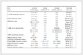
Table 1. Electrochemical kinetics parameters obtained from the equivalent circuit fitting of the EIS for the LFCP/C-FP and LFCP/C-FO electrodes
| Sample | Re/Ω | Rrt/Ω | D/(cm2·s-1) |
| LFCP/C-FP | 6.17 | 110.9 | 2.08×10⁻¹⁴ |
| LFCP/C-F0 | 5.83 | 48.75 | 6.39×10⁻¹⁴ |
 下载: 导出CSV

 扫一扫看文章


扫一扫关注我们

