 Figure 1.
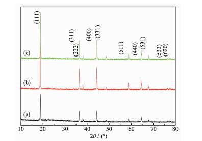
XRD pattern of pristine and coated LiNi0.5Mn1.5O4 (a) pristine LiNi0.5Mn1.5O4; (b) 5% Li3PO4 coated-LiNi0.5Mn1.5O4; (c) 10% Li3PO4 coated-LiNi0.5Mn1.5O4
Figure 1.
XRD pattern of pristine and coated LiNi0.5Mn1.5O4 (a) pristine LiNi0.5Mn1.5O4; (b) 5% Li3PO4 coated-LiNi0.5Mn1.5O4; (c) 10% Li3PO4 coated-LiNi0.5Mn1.5O4
Citation:
REN Ning, LU Shi-Gang. Li3PO4 Surface Modification to Improve Performance of LiNi0.5Mn1.5O4 Cathode Material[J]. Chinese Journal of Inorganic Chemistry,
2016, 32(3): 499-507.
doi:
10.11862/CJIC.2016.068

Li3PO4表面修饰提高球形LiNi0.5Mn1.5O4正极材料的性能
摘要:
通过共沉淀法制备了球形LiNi0.5Mn1.5O4@Li3PO4复合材料, 并采用X射线衍射 (XRD)、扫描电镜 (SEM)、红外光谱 (FT-IR)、循环伏安 (CV)、电化学阻抗谱 (EIS) 及充放电测试研究了其结构与电化学性能.XRD和SEM表明, Li3PO4包覆影响了球形LiNi0.5Mn1.5O4的晶格常数.CV和EIS表明, 质量百分数5% Li3PO4包覆的LiNi0.5Mn1.5O4具有比纯LiNi0.5Mn1.5O4更高的锂离子嵌脱可逆性, 更大的锂离子扩散系数和更小的电荷转移电阻, 说明在锂离子扩散过程中, 质量百分数5%Li3PO4包覆的LiNi0.5Mn1.5O4具有更高的电子电导率.充放电测试表明, 原位Li3PO4改性提高了材料的电子电导率、电化学活性, 进而提高了高倍率放电容量.质量百分数5% Li3PO4包覆的LiNi0.5Mn1.5O4提高的电化学性能归因于Li3PO4的包覆、纳米颗粒组成球形的粒径引起的高的电子电导率和小的电化学极化.
English
Li3PO4 Surface Modification to Improve Performance of LiNi0.5Mn1.5O4 Cathode Material
Abstract:
Spherical LiNi0.5Mn1.5O4@Li3PO4 composite was prepared by a co-precipitation method. The structure and electrochemical performance were investigated by X-ray powder diffraction (XRD), scanning electron microscope (SEM), FT-IR spectroscopy, cyclic voltammetry (CV), electrochemical impedance spectroscopy (EIS) and charge-discharge measurements. XRD and SEM shows that Li3PO4 coating influence the lattice parameter of LiNi0.5Mn1.5O4 composed of spherical particle size. CV and EIS imply that 5% (mass percent) Li3PO4-coated LiNi0.5Mn1.5O4 has higher reversible intercalation and deintercalation of Li+, larger lithium-ion diffusion coefficient and smaller charge transfer resistance corresponding to a much higher conductivity than those of pristine LiNi0.5Mn1.5O4 corresponding to the extraction of Li+ ions. Charge-discharge test reveals that the in situ Li3PO4 modifying improves the electronic conductivity of the electrode in the local environment, electrochemical activity, and then results in their relatively higher capacity at high charge-discharge rate. The enhanced performance of 5% (mass percent) Li3PO4-coated LiNi0.5Mn1.5O4 is ascribed to the improved electronic conduction and the reduced polarization resulting from the Li3PO4 modification together with sphere-like particles composed of nano particle LiNi0.5Mn1.5O4.
-
Key words:
- lithium-ion battery
- / cathode materials
- / surface coating
- / electrochemical performance
-
0 Introduction
Spinel LiMn2O4 is one of the most promising cathode for electric vehicles (EVs), hybrid electrical vehicles (HEVs), and plug-in hybrid vehicles (PHEVs) due to its adequate capacity, economical production, safety, low toxicity and high thermal stability [1]. Unfortunately, poor rate capability, cyclability and high-temperature performance limit its further applica-tion for power batteries due to the Jahn-Teller distortion[2]. In addition, a further improvement in terms of cycling life and energy density is still required to fulfill the demands of these applications. As we know, the partial substitution by other metals for Mn in LiMn2O4 could stabilize the crystal structure and improve the cycling performance[3-5]. Among all doped LiMxMn2-xO4, the Ni-doped spinel LiNi0.5Mn1.5O4 has attracted great interests for its good rate capability, high theoretical capacity (147 mAh·g-1) and much high discharge voltage at around 4.7 V corresponding to the redox reactions of Ni2+/Ni3+ and Ni3+/Ni4+ redox couples [6]. However, LiNi0.5Mn1.5O4 usually losses oxygen and disproportionates to a spinel and LixNi1-xO or NiO when it is heated above 650 ℃[7]. Hence, this LiNi0.5Mn1.5O4 compound still has a non-negligible capacity fading during cycling due to the structural and chemical instabilities resulted from the presence of high spin Mn3+ ions. Hence, morphology controlling[8], doping[9-12] and surface coating[13-17] were considered as effective ways to improve the electrochemical perfor-mance of LiNi0.5Mn1.5O4 materials. Various morphologies of LiNi0.5Mn1.5O4, such as nanoparticles[18], nanorods[19], and microspheres[20], have been successfully fabricated to improve the electrochemical performance. However, nanomaterial frequently results in a low volumetric energy density of the cell. A variety of methods used to prepare LiNi0.5Mn1.5O4 have been developed, including solid-state reaction[21], sol-gel[22], emulsion drying[23], composite carbonate process[24], hydrothermal method[25] and co-precipitation[26]. Among those routes to preparation of cathode materials, the co-precipitation is one of the most effective and conventional and inexpensive methods to synthesize the final product of LiNi0.5Mn1.5O4[27]. Li3PO4 is known to be a fast solid lithium ionic conductor[28], and Li3PO4 coating has been used to improve the electrochemical performance of LiMn2O4[29], LiCoO2[30], LiFePO4[31] cathode materials. With this consideration, we have developed a novel ethanol-assisted co-precipitation method to synthesize spherical LiNi0.5Mn1.5O4 and Li3PO4-coated LiNi0.5Mn1.5O4 composites. With this method, the Mn3+ in the LiNi0.5Mn1.5O4 can be efficiently limited. Consequently, the overall electrochemical performance of the LiNi0.5Mn1.5O4 can be obviously improved.
1 Experimental
1.1 Material preparation
For the preparation of Li3PO4, a certain amount of LiOH and H3PO4 was dissolved in deionized water, and then heated in water bath with mechanical stirring at 80 ℃ for 6 h. Then the turbid liquid was filtered, and dried in vacuum drying oven for 12 h at 120 ℃, yielding Li3PO4 powders. LiNi0.5Mn1.5O4 powders were prepared by ethanol-assisted oxalic acid co-precipitation method. The NiSO4·6H2O and MnSO4·H2O were dissolved in the mixed solution of deionized water and ethanol with a molar ratios of 1:2, and named solution 1. The NH4HCO3 was also dissolved in the deionized water, and the molar ratio between NH4HCO3 and sulphate (NiSO4·6H2O+MnSO4·H2O) is 1:1, and named solution 2. The solution 1 and solution 2 were mixed, and then the resulting precursor solution was transferred to a Teflon-lined stainless steel autoclave and heated at 200 ℃ for 10 h. The powder deposited at the bottom of the reactor was collected by centrifugation. The powder and appropriate Li2CO3 was mixed, then the precursors were heat treated at 800 ℃ for 12 h at ambient condition, and then treated at 600 ℃ for 6 h, and then air-cooled to the room temperature, yielding LiNi0.5Mn1.5O4 dark powders.
For the preparation of LiNi0.5Mn1.5O4@Li3PO4, the Li3PO4 was added to the mixture of solution 1 and solution 2, and transferred to a Teflon-lined stainless steel autoclave and heated at 200 ℃ for 10 h. The following synthesis process is the same for LiNi0.5Mn1.5O4 powders. The predetermined amounts of Li3PO4 in LiNi0.5Mn1.5O4 are 5% and 10% (mass percent), respectively.
1.2 Material characterization
The crystal structure was characterized by X-ray diffractometry (XRD) measurements performed on a Rigaku instrument with Cu Kα1 radiation (45 kV, 50 mA, step size=0.02°, 10° < 2θ < 90°). The morphology and the microstructure of the products were examined by a scanning electron microscopy (SEM, SU8000). FT-IR spectroscopy of the samples was performed using a Nicolet Nexus 6700 FT-IR spectrophotometer with a resolution of 4 cm-1. A total of 1.5 mg sample dried at 120 ℃ was thoroughly mixed with 200 mg KBr and pressed into pellets and the scans were performed immediately to avoid water absorption. The frequency range was 800~400 cm-1.
1.3 Electrochemical analysis
The electrochemical characterizations were performed using CR2025 coin-type cell. The working electrode was prepared by mixing 80% (mass percent) active material, 10% (mass percent) conductive super P carbon and 10% (mass percent) polyvinylidene fluoride (PVDF) as binder in N-methyl pyrrolidinone (NMP). After being uniformly coated onto a copper foil, the slurry was dried in a vacuum at 120 ℃ for 10 h. A solution of 1 mol·L-1 LiPF6 dissolved in a mixture of ethylene carbonate and dimethyl carbonate (1:1, in volume) was used as the electrolyte and porous polypropylene Celgard 2300 was used as separator. The charge-discharge measurements were recorded on multichannel Land Battery Test System (Wuhan Jinnuo, China) at room temperature between 3.5 and 4.95 V (vs Li/Li+) carried out at different charge-discharge rates. Cyclic voltammetry (CV) test was carried out on a CHI 1000C electrochemical workstation with a voltage between 3.5 and 4.95 V at a scanning rate of 0.05 mV·s-1. Electrochemical impedance spectroscopy (EIS) of OCV (open circuit voltage, before cycle) is measured by a Princeton P4000 electrochemical working station over a frequency range from 0.01 Hz to 10 kHz at a potentiostatic signal amplitude of 5 mV. The open circuit voltage is about 3.2 V.
2 Results and discussion
Fig. 1 shows the X-ray diffraction patterns of the pristine and Li3PO4 coated-LiNi0.5Mn1.5O4 powders. All the sharp diffraction peaks can be attributed to the well-defined cubic spinel structure of LiNi0.5Mn1.5O4. This indicates that the Li3PO4 coating does not change the spinel structure of LiNi0.5Mn1.5O4. In addition, no trace of impurity phase (such as LixNi1-xO or NiO) is detected. However, the characteristic Li3PO4 diffraction peak is not obvious, indicating that the Li3PO4 in the LiNi0.5Mn1.5O4/Li3PO4 composites are amorphous during the calcination process. The strong reflections located at 19.1°, 36.8°, 38.5°, 44.5°, 48.8°, 58.9°, 64.8°, 68.1°, 76.6° and 77.6° can be indexed to the (111), (311), (222), (400), (331), (511), (440), (531), (533) and (620) diffractions, respectively. It is well known that LiNi0.5Mn1.5O4 has two different space groups, Fd3m or P4332 depending on Ni ordering in the lattice. In the Fd3m structure, Li+ ions occupy the tetrahedral (8a) sites; Mn or Ni ions reside at the octahedral (16d) sites random; and O2-ions are located at (32e) sites. In P4332 structure the Li atoms are located at 8c sites, Ni atoms at 4a sites, Mn atoms at 12d sites, and O atoms at 8c and 24e sites[32-33]. In LiNi0.5Mn1.5O4 with P4332 space group, it can be found a decrease of lattice parameter and symmetry caused by cation ordering, and weak superstructure reflections around 2θ≈15°, 24°, 35°, 40°, 46°, 47°, 57°, and 75° can be found [34]. However, the scanning rate in this work was too fast for us to detect them.
Figure 1.
XRD pattern of pristine and coated LiNi0.5Mn1.5O4 (a) pristine LiNi0.5Mn1.5O4; (b) 5% Li3PO4 coated-LiNi0.5Mn1.5O4; (c) 10% Li3PO4 coated-LiNi0.5Mn1.5O4
In fact, the structural difference between these two space groups is hardly to be clearly distinguished by X-ray diffraction because of the similar scattering factors of Ni and Mn. FT-IR spectroscopy has proved to be an effective technique in qualitatively resolving the cation ordering (Fig. 2). It has been reported that the peak at about 623 cm-1 in Fd3m phase are more intensive than those at 593 cm-1, which is contrary to the P4332 phase[35]. In addition, three new peaks at about 650, 470 and 432 cm-1 are absent in Fd3m structure. Hence, it can be concluded that pristine LiNi0.5Mn1.5O4 and 10% Li3PO4-coated LiNi0.5Mn1.5O4 has a space P4332 groups. However, the peak of 5% Li3PO4-coated LiNi0.5Mn1.5O4 at about 623 cm-1 are weaker than that at 593 cm-1, revealing that 5% Li3PO4-coated LiNi0.5Mn1.5O4 has a P4332 and Fd3m mixed phase. This indicates that 5% Li3PO4-coated LiNi0.5Mn1.5O4 has the biggest degree of disorder among all samples. It has been reported that the crystal with disordered space groups have the better transmission path of electronic and Li+ [36]. Therefore, it can be concluded that the 5% Li3PO4-coated LiNi0.5Mn1.5O4 has the better electrochemical performance than ordered LiMn1.5Ni0.5O4 and 10% Li3PO4-coated LiNi0.5Mn1.5O4.
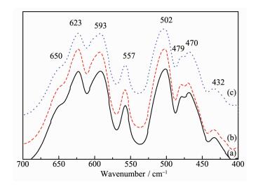 Figure 2.
FT-IR of pristine and coated LiNi0.5Mn1.5O4 (a) pristine LiNi0.5Mn1.5O4; (b) 5% Li3PO4 coated-LiNi0.5Mn1.5O4; (c) 10% Li3PO4 coated-LiNi0.5Mn1.5O4
Figure 2.
FT-IR of pristine and coated LiNi0.5Mn1.5O4 (a) pristine LiNi0.5Mn1.5O4; (b) 5% Li3PO4 coated-LiNi0.5Mn1.5O4; (c) 10% Li3PO4 coated-LiNi0.5Mn1.5O4
Fig. 3 shows the SEM images of the pristine and Li3PO4 coated-LiNi0.5Mn1.5O4 powders. It can be found that the particles of all samples exist as homogeneous sphere-like particles. The diameters of the spheres distribute within the range of 1~1.5 μm. The sphere-like particles are composed of nano particle LiNi0.5Mn1.5O4 at about 100 nm. Very small particles of coated LiNi0.5Mn1.5O4 powders were found to be highly dispersed on the coated Li3PO4 particles as shown in Fig. 3b and Fig. 3c. In addition, the surface morphology of pristine LiNi0.5Mn1.5O4 is extremely smooth. From a comparison of this three powders surface morphology, it can be speculated that the surface of the prepared LiNi0.5Mn1.5O4 is covered with small Li3PO4. This indicates that the surface modification leads to formation of uniform coating.
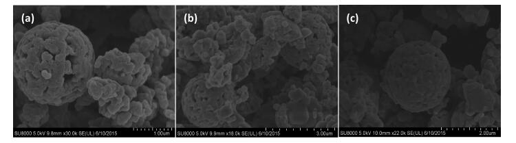 Figure 3.
SEM images of pristine and coated LiNi0.5Mn1.5O4 (a) pristine LiNi0.5Mn1.5O4; (b) 5% Li3PO4 coated-LiNi0.5Mn1.5O4;
(c) 10% Li3PO4 coated-LiNi0.5Mn1.5O4
Figure 3.
SEM images of pristine and coated LiNi0.5Mn1.5O4 (a) pristine LiNi0.5Mn1.5O4; (b) 5% Li3PO4 coated-LiNi0.5Mn1.5O4;
(c) 10% Li3PO4 coated-LiNi0.5Mn1.5O4
Fig. 4 examines the initial charge and discharge behaviors of a series of Li3PO4-coated LiNi0.5Mn1.5O4 materials at room temperature in 3.5~4.95 V range, at a current density of 0.2C. The initial discharge capa-cities of pristine and 5, 10% Li3PO4-coated LiNi0.5Mn1.5O4 cathode material are 118.1, 131.6 and 132.9 mAh·g-1, respectively. Obviously, Li3PO4 coating increases the initial discharge capacity of LiNi0.5Mn1.5O4 cathode.
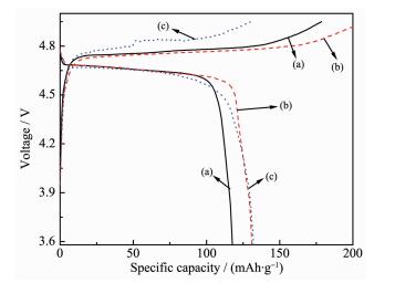 Figure 4.
Initial charge-discharge curves of pristine and coated LiNi0.5Mn1.5O4 (a) pristine LiNi0.5Mn1.5O4;
(b) 5% Li3PO4 coated-LiNi0.5Mn1.5O4; (c) 10% Li3PO4 coated-LiNi0.5Mn1.5O4
Figure 4.
Initial charge-discharge curves of pristine and coated LiNi0.5Mn1.5O4 (a) pristine LiNi0.5Mn1.5O4;
(b) 5% Li3PO4 coated-LiNi0.5Mn1.5O4; (c) 10% Li3PO4 coated-LiNi0.5Mn1.5O4
Fig. 5 shows the rate capabilities for three samples. The cells were discharged at increasingly higher currents from 0.2C to 0.5C rates at room temperature. It can be found that the capacity difference between the pristine LiNi0.5Mn1.5O4 electrode and 5% Li3PO4-coated LiNi0.5Mn1.5O4 electrode progressively increased. At the 0.5C charge-discharge rate after 20 cycles, the discharge capacity was 107.4 mAh·g-1 for the pristine LiNi0.5Mn1.5O4 material (90.9% of the capacity at 0.2C), and 120 mAh·g-1 for the 5% Li3PO4-coated LiNi0.5Mn1.5O4 material (91.2% at 0.2C). This result indicates that the Li3PO4 coating improves the rate capability of LiNi0.5Mn1.5O4 as well as its capability to store Li ions. The reason may be suggested as follows.
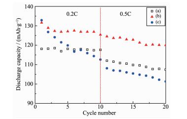 Figure 5.
Rate performance of pristine and coated LiNi0.5Mn1.5O4 (a) pristine LiNi0.5Mn1.5O4;
(b) 5% Li3PO4 coated-LiNi0.5Mn1.5O4;
(c) 10% Li3PO4 coated-LiNi0.5Mn1.5O4
Figure 5.
Rate performance of pristine and coated LiNi0.5Mn1.5O4 (a) pristine LiNi0.5Mn1.5O4;
(b) 5% Li3PO4 coated-LiNi0.5Mn1.5O4;
(c) 10% Li3PO4 coated-LiNi0.5Mn1.5O4
Trace water impurity in the electrolyte would cause the liberation of acid HF through the decom-position of LiPF6-based electrolyte. The chemical reactions were proposed as follows[37-38]:
HF will dissolve LiNi0.5Mn1.5O4 proposed as follows[39]:
Therefore, it can be concluded that a uniform Li3PO4 coating on the surface of the LiNi0.5Mn1.5O4 not only can act as an ion-conductive layer, but also acts to suppress the decomposition of Mn and Ni during cycling, as demonstrated in Fig. 6. However, 10% Li3PO4-coated LiNi0.5Mn1.5O4 electrode shows an unsati-sfactory rate performance, indicating that the contents of coated Li3PO4 have strong impact on the rate capability of LiNi0.5Mn1.5O4 electrode. Therefore, it is important to optimize the coated Li3PO4 content in order achieve a good cell performance.
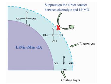 Figure 6.
Schematic illustration of how the Li3PO4 layer acts as a conductive and protective layer to suppress the direct contact between electrolyte and LNMO and decomposition of electrolyte
Figure 6.
Schematic illustration of how the Li3PO4 layer acts as a conductive and protective layer to suppress the direct contact between electrolyte and LNMO and decomposition of electrolyte
Fig. 7 presents typical cyclic voltammograms (CVs) of pristine and Li3PO4 coated-LiNi0.5Mn1.5O4. The intense and sharp reduction/oxidation peaks of Ni2+/Ni4+ are observed at around 4.7 V in pristine and Li3PO4 coated-LiNi0.5Mn1.5O4, with trace amount of the couple of Mn4+/Mn3+ that usually appears at around 4.0 V shown in inset. The appearance of 4 V peak was due to Mn3+ which was formed by the oxygen loss during high temperature calcinations. It can be found that the CV curve of pristine LiNi0.5Mn1.5O4 presents a much more obvious redox peaks in the potential region around 4.0 V (from the redox couples Mn4+/Mn3+), which means that the oxygen deficiency is more severe from the oxygen loss due to the Li3PO4 coating[40]. This indicates that Li3PO4 coating destroys the ordering of Ni and Mn ions, and the proportion of Fd3m spinel increase with the rise of Li3PO4 content.
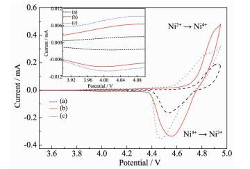 Figure 7.
CV curves of pristine and coated LiNi0.5Mn1.5O4 (a) pristine LiNi0.5Mn1.5O4; (b) 5% Li3PO4 coated-LiNi0.5Mn1.5O4; (c) 10% Li3PO4 coated-LiNi0.5Mn1.5O4
Figure 7.
CV curves of pristine and coated LiNi0.5Mn1.5O4 (a) pristine LiNi0.5Mn1.5O4; (b) 5% Li3PO4 coated-LiNi0.5Mn1.5O4; (c) 10% Li3PO4 coated-LiNi0.5Mn1.5O4
The potential differences between anodic and cathodic peaks reflect the polarization degree of the electrode[41]. The potential difference of the pristine and Li3PO4 coated-LiNi0.5Mn1.5O4 electrodes between oxidation and reduction peaks is listed in Table 1. It can be found that the potential difference (Δφp=φpa-φpc) of pristine LiNi0.5Mn1.5O4 is 393 mV, obviously much larger than those for the pristine and Li3PO4 coated-LiNi0.5Mn1.5O4 electrodes. 5% Li3PO4-coated LiNi0.5Mn1.5O4 sample shows the lowest potential interval between anodic and cathodic peak (353 mV), which indicate that the right amount of Li3PO4 coating is favorable for reducing the electrode polarization. This means that 5% Li3PO4 coated-LiNi0.5Mn1.5O4 has the excellent electrochemical reversibility and faster lithium insertion/extraction kinetics. This observation confirms that right amount of Li3PO4 coating enhances the reversibility of the LiNi0.5Mn1.5O4, and then exhibits reversibility and good rate capability.
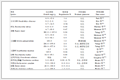 Table 1.
Peak potential differences of CV test for pristine and coated LiNi0.5Mn1.5O4 material
Table 1.
Peak potential differences of CV test for pristine and coated LiNi0.5Mn1.5O4 material
Sample φpa/V φpc/V △φp / mV LiNi0.5Mn1.5O4 4.924 4.531 393 5% Li3PO4-coated LiNi0.5Mn1.5O4 4.920 4.567 353 10% Li3PO4-coated LiNi0.5Mn1.5O4 4.855 4.473 382 Table 1. Peak potential differences of CV test for pristine and coated LiNi0.5Mn1.5O4 materialThe kinetics of lithium ion extraction and insertion of the pristine and Li3PO4 coated-LiNi0.5Mn1.5O4 electrodes were further investigated by EIS. Fig. 8 shows the Nyquist plots of all samples, and the inset is the equivalent circuit used to fit impedance spectra. The circuit consists of Rs (ohmic resistance), Rf (the resistance of a solid electrolyte interphase film), Cf (the capacitance of a solid electrolyte interphase film), Rct (charge-transfer resistance), Cdl (double layer capacitance for lithium-ion intercalation) and W (Warburg impedance of solid phase diffusion)[42-43]. The fitted results are summarized in Table 2.
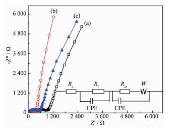 Figure 8.
Nyquist plots of pristine and coated LiNi0.5Mn1.5O4 (a) pristine LiNi0.5Mn1.5O4; (b) 5% Li3PO4 coated-LiNi0.5Mn1.5O4; (c) 10% Li3PO4 coated-LiNi0.5Mn1.5O4
Table 2.
Some fitting parameters obtained by EIS
Figure 8.
Nyquist plots of pristine and coated LiNi0.5Mn1.5O4 (a) pristine LiNi0.5Mn1.5O4; (b) 5% Li3PO4 coated-LiNi0.5Mn1.5O4; (c) 10% Li3PO4 coated-LiNi0.5Mn1.5O4
Table 2.
Some fitting parameters obtained by EIS
Sample Rs/Ω Rct/Ω i0 / (mA·cm-2) DLi/ (cm2·s-1) LiNi0.5Mn1.5O4 9.488 1 855 0.009 7.89×10⁻¹⁷ 5% Li3PO4 coated-LiNi0.5Mn1.5O4 6.684 545 0.031 2.72×10⁻¹⁶ 10% Li3PO4 coated-LiNi0.5Mn1.5O4 7.158 802 0.02! 6.11×lO-17 Table 2. Some fitting parameters obtained by EISThe Rs reflects electric conductivity of the electrolyte, separator, and electrodes. It can be found that 5% Li3PO4 coated-LiNi0.5Mn1.5O4 has the smallest ohmic resistance among all samples, indicating a high conductivity between electrolyte and electrodes. Table 2 shows that the charge transfer resistance of Li3PO4 coated-LiNi0.5Mn1.5O4 electrode is much lower than that of the pristine one. This reveals that Li3PO4 modifica-tion is favorable to improve upon the electronic cond-uctivity. In addition, 5% Li3PO4 coated-LiNi0.5Mn1.5O4 has the smallest charge transfer resistance among all samples. It is reasonable to infer that the lowest charge transfer resistance of 5% Li3PO4 coated-LiNi0.5Mn1.5O4 electrode corresponds with the smallest electrochem-ical polarization, and then lead to the best electro-chemical performance. Afterwards, the exchange current density, i0, can be calculated by means of the charge transfer resistance,
where R is the gas constant (8.314 5 J·mol-1·K-1); T is the absolute temperature (298.15 K); F is the Faraday′s constant (96 485 C·mol-1), and A is the area of the electrode surface (1.54 cm2). The calculated results are given in Table 2. Obviously, 5% Li3PO4 coated-LiNi0.5Mn1.5O4 has the biggest c exchange current density among all samples, revealing the lowest intercalation/deintercalation resistance and highest electrochemical activity.
As we know, lithium ion diffusion rate also plays an important role in accelerating lithium ion insertion/extraction during the charge/discharge process[44]. The diffusion coefficient of lithium ion (DLi) can be calculated from the plots in the low frequency region, and can be obtained according to the following equations[45]:
where ω is the angular frequency in the low frequency region; R is the gas constant (8.314 5 J·mol-1·K-1); T is the absolute temperature (298.15 K); n is the number of electrons transferred in the half-reaction for the redox couple (n=1); F is the Faraday′s constant (96 485 C·mol-1); A is the area of the electrode surface (1.54 cm2); CLi is the molar concentration of Li+ ions calculated by the molar volume (2.37×10⁻² mol·cm-3)[46], and σ is the Warburg impedance coefficient, which is relative to Zre-σ can be obtained from the slope of the lines in Fig. 9.
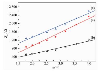 Figure 9.
Graph of Zre plotted against ω-1/2 in the low-frequency region for the pristine and coated LiNi0.5Mn1.5O4 (a) pristine LiNi0.5Mn1.5O4; (b) 5% Li3PO4 coated-LiNi0.5Mn1.5O4; (c) 10% Li3PO4 coated-LiNi0.5Mn1.5O4
Figure 9.
Graph of Zre plotted against ω-1/2 in the low-frequency region for the pristine and coated LiNi0.5Mn1.5O4 (a) pristine LiNi0.5Mn1.5O4; (b) 5% Li3PO4 coated-LiNi0.5Mn1.5O4; (c) 10% Li3PO4 coated-LiNi0.5Mn1.5O4
The calculated diffusion coefficient of lithium ion is given in Table 2. For the 5% Li3PO4-coated LiNi0.5 Mn1.5O4, lithium-ion diffusion coefficient is estimated to be 2.72×10⁻¹⁶ cm2·s-1, which is larger than that of 7.89×10⁻¹⁷ cm2·s-1 for pristine LiNi0.5Mn1.5O4 cathode. Considering the similar particle sizes and morpho-logies of three samples, it can be concluded that the improved lithium-diffusivity might be attributed to the modification of Li3PO4. Based on the above calcula-tion, the charge transfer resistance and lithium-ion diffusion coefficient indicate that Li3PO4 coating can enhance the conductivity of LiNi0.5Mn1.5O4, enabling much easier charge transfer at the interface between the electrode and the electrolyte.
Beaulieu et al reported that lithium ions can react with the grain boundary phase in polycrystalline materials or the liquid electrolyte at the solid/liquid interface[47]. According to the model of the LiNi0.5Mn1.5O4-Li3PO4 composites shown in Fig. 10, in situ coated Li3PO4 is tightly combined with LiNi0.5Mn1.5O4, and then many LiNi0.5Mn1.5O4-Li3PO4 phase interfaces can be formed. Li3PO4 is a super ionic conductors, and the Li ionic conductivity of Li3PO4 (about 10-6 S·m-1) facilitates the charge transfer reactions on the electrode/electrolyte interface[48]. The combination of in situ coated Li3PO4 can improve the Li diffusion coefficient and reduce the charge transfer resistance. The LiNi0.5Mn1.5O4-Li3PO4 phase interfaces can also store electrolyte and provide more places for the insertion/extraction reactions of lithium ions, and then improve the reaction kinetics and reduce electro-chemical polarization during cycling. Thus it may be a reason for the superior high rate capability of Li3PO4-coated LiNi0.5Mn1.5O4. Hence, Li3PO4 in situ modifica-tion is an effective way to improve the electrochemical performance of LiNi0.5Mn1.5O4.
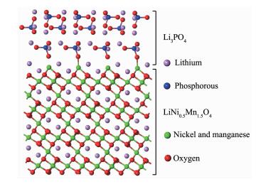 Figure 10.
odel of the LiNi0.5Mn1.5O4-Li3PO4 composites
Figure 10.
odel of the LiNi0.5Mn1.5O4-Li3PO4 composites
3 Conclusions
Surface modification of the spherical LiNi0.5Mn1.5O4 is successfully done by Li3PO4 coating by the precipitation method. The combination of in situ coated Li3PO4 can improve the Li diffusion coefficient and reduce the charge transfer resistance of LiNi0.5Mn1.5O4, and then provides more places for the insertion/extraction reactions of lithium ions, leading to the improvement of the reaction kinetics. 5% Li3PO4-coated LiNi0.5Mn1.5O4 exhibits the lowest charge-transfer resistance and the highest lithium diffusion coefficient among all samples, and it thus shows higher discharge capacities and better rate capability than the pristine material. The improved electrochemical properties also can be attributed that the Li3PO4 coating layer retards the side reactions of the active material with electrolyte. Hence, it is reasonable to infer that the Li3PO4 coating would be an effective way to improve the electrochemical properties of LiNi0.5Mn1.5O4 cathode materials.
-
-
[1]
刘东强, 吁霁, 孙玉恒, 等.无机化学学报, 2007, 23 (1):41-45 http://www.wjhxxb.cn/wjhxxbcn/ch/reader/view_abstract.aspx?flag=1&file_no=20070106&journal_id=wjhxxbcnLIU Dong-Qiang, YU Ji, SUN Yu-Heng, et al. Chinese J. Inorg. Chem., 2007, 23 (1):41-45 http://www.wjhxxb.cn/wjhxxbcn/ch/reader/view_abstract.aspx?flag=1&file_no=20070106&journal_id=wjhxxbcn
-
[2]
陈召勇, 刘兴泉, 高利珍, 等.无机化学学报, 2001, 17(3):325-330 http://www.wjhxxb.cn/wjhxxbcn/ch/reader/view_abstract.aspx?flag=1&file_no=20010304&journal_id=wjhxxbcnCHEN Zhao-Yong, LIU Xing-Quan, GAO Li-Zhen, et al. Chinese J. Inorg. Chem., 2001, 17(3):325-330 http://www.wjhxxb.cn/wjhxxbcn/ch/reader/view_abstract.aspx?flag=1&file_no=20010304&journal_id=wjhxxbcn
-
[3]
王超, 刘兴泉, 刘宏基, 等.无机化学学报, 2012, 28(9):1835-1842 http://www.wjhxxb.cn/wjhxxbcn/ch/reader/view_abstract.aspx?flag=1&file_no=20120907&journal_id=wjhxxbcnWANG Chao, LIU Xing-Quan, LIU Hong-Ji, et al. Chinese J. Inorg. Chem., 2012, 28(9):1835-1842 http://www.wjhxxb.cn/wjhxxbcn/ch/reader/view_abstract.aspx?flag=1&file_no=20120907&journal_id=wjhxxbcn
-
[4]
刘兴泉, 钟辉, 唐毅, 等.无机化学学报, 2003, 19 (5):467-472 http://www.wjhxxb.cn/wjhxxbcn/ch/reader/view_abstract.aspx?flag=1&file_no=20030504&journal_id=wjhxxbcnLIU Xing-Quan, ZHONG Hui, TANG Yi, et al. Chinese J. Inorg. Chem., 2003, 19 (5):467-472 http://www.wjhxxb.cn/wjhxxbcn/ch/reader/view_abstract.aspx?flag=1&file_no=20030504&journal_id=wjhxxbcn
-
[5]
Yi T F, Yin L C, Ma Y Q, et al. Ceram. Int., 2013, 39(4): 4673-4678 doi: 10.1016/j.ceramint.2012.10.256
-
[6]
聂翔, 郭孝东, 钟本和, 等.无机化学学报, 2012, 28(12):2573-2580 http://www.wjhxxb.cn/wjhxxbcn/ch/reader/view_abstract.aspx?flag=1&file_no=20121211&journal_id=wjhxxbcnNIE Xiang, Guo Xiao-Dong, ZHONG Ben-He, et al. Chinese J. Inorg. Chem., 2012, 28(12):2573-2580 http://www.wjhxxb.cn/wjhxxbcn/ch/reader/view_abstract.aspx?flag=1&file_no=20121211&journal_id=wjhxxbcn
-
[7]
Zhong Q, Bonakdarpour A, Zhong M, et al. J. Electrochem. Soc., 1997, 144(1):205-213 doi: 10.1149/1.1837386
-
[8]
Wang J, Lin W, Wu B, et al. J. Mater. Chem. A, 2014, 2(48): 16434-16442 http://pubs.rsc.org/en/content/articlelanding/2014/ta/c4ta02903h#!divAbstract
-
[9]
张胜利, 李良玉, 宋延华, 等.稀有金属材料与工程, 2010, 39(3): 515-518 http://www.cnki.com.cn/Article/CJFDTotal-COSE201003034.htmZHANG Sheng-Li, LI Liang-YU, SONG Yan-Hua, et al. Rare Metal Mater. Eng., 2010, 39(3): 515-518 http://www.cnki.com.cn/Article/CJFDTotal-COSE201003034.htm
-
[10]
邓海福, 聂平, 申来法, 等.化学进展, 2014, 26(6):939-949 http://www.cnki.com.cn/Article/CJFDTotal-HXJZ201406004.htmDENG Hai-Fu, NIE Ping, SHEN Lai-Fa, et al. Prog. Chem., 2014, 26(6):939-949 http://www.cnki.com.cn/Article/CJFDTotal-HXJZ201406004.htm
-
[11]
Wang S, Li P, Shao L, et al. Ceram. Int., 2015, 41(1):1347-1353 doi: 10.1016/j.ceramint.2014.09.067
-
[12]
Li H, Luo Y, Xie J, et al. J. Alloys Compd., 2015, 639:346-351 doi: 10.1016/j.jallcom.2015.03.114
-
[13]
王兆翔, 陈立泉, 黄学杰.化学进展, 2011, 23 (2/3):284-301 http://www.cnki.com.cn/Article/CJFDTotal-HXJZ2011Z1005.htmWANG Zhao-Xiang, CHEN Li-Quan, HUANG Xue-Jie. Prog. Chem., 2011, 23 (2/3):284-301 http://www.cnki.com.cn/Article/CJFDTotal-HXJZ2011Z1005.htm
-
[14]
Konishi H, Suzuki K, Taminato S, et al. J. Power Sources, 2014, 269:293-298 doi: 10.1016/j.jpowsour.2014.05.052
-
[15]
Li X, Guo W, Liu Y, et al. Electrochim. Acta, 2014, 116: 278-283 doi: 10.1016/j.electacta.2013.11.055
-
[16]
Arrebola J C, Caballero A, Hernán L, et al. J. Power Sources, 2010, 195(13):4278-4284 doi: 10.1016/j.jpowsour.2010.01.004
-
[17]
Kim J W, Kim D H, Oh D Y, et al. J. Power Sources, 2015, 274:1254-1262 doi: 10.1016/j.jpowsour.2014.10.207
-
[18]
Elia G A, Nobili F, Tossici R, et al. J. Power Sources, 2015, 275:227-233 doi: 10.1016/j.jpowsour.2014.10.144
-
[19]
Zhang X, Cheng F, Yang J, et al. Nano Lett., 2013, 13(6): 2822-2825 doi: 10.1021/nl401072x
-
[20]
Zhu Z, Zhang D, Yan H, et al. J. Mater. Chem. A, 2013, 1 (18):5492-5496 doi: 10.1039/c3ta10980a
-
[21]
Zhu Z, Yan H, Zhang D, et al. J. Power Sources, 2013, 224: 13-19 doi: 10.1016/j.jpowsour.2012.09.043
-
[22]
Liu G, Kong X, Sun H, et al. Ceram. Int., 2014, 40(9):14391-14395 doi: 10.1016/j.ceramint.2014.06.032
-
[23]
Myung S T, Komaba S, Kumagai N, et al. Electrochim. Acta, 2002, 47(15):2543-2549 doi: 10.1016/S0013-4686(02)00131-7
-
[24]
Wen L, Lu Q, Xu G.. Electrochim. Acta, 2006, 51(21):4388-4392 doi: 10.1016/j.electacta.2005.12.018
-
[25]
Xue Y, Wang Z, Yu F, et al. J. Mater. Chem. A, 2014, 2(12): 4185-4191 doi: 10.1039/c3ta14567k
-
[26]
Feng J, Huang Z, Guo C, et al. Appl. Mater. Interfaces, 2013, 5(20):10227-10232 doi: 10.1021/am4029526
-
[27]
Yi T F, Fang Z K, Xie Y, et al. Electrochim. Acta, 2014, 147:250-256 doi: 10.1016/j.electacta.2014.09.119
-
[28]
Zhang S Q, Xie S, Chen C H.. Mater. Sci. Eng. B, 2005, 121 (1/2):160-165 http://www.sciencedirect.com/science/article/pii/S0921510705002138
-
[29]
Li X, Yang R, Cheng B, et al. Mater. Lett., 2012, 66(1):168-171 doi: 10.1016/j.matlet.2011.08.075
-
[30]
Jin N L Y, Chen C H, Wei S Q.. Electrochem. Solid-State Lett., 2006, 9(6):A273-A276 doi: 10.1149/1.2188081
-
[31]
Zhao S X, Ding H, Wang Y C, et al. J. Alloys Compd., 2013, 566:206-211 doi: 10.1016/j.jallcom.2013.03.041
-
[32]
Wang L, Li H, Huang X, et al. Solid State Ionics, 2011, 193 (1):32-38 doi: 10.1016/j.ssi.2011.04.007
-
[33]
Yi T F, Zhu Y R, Zhu R S.. Solid State Ionics, 2008, 179 (38):2132-2136 doi: 10.1016/j.ssi.2008.07.016
-
[34]
Kim J H, Yoon C S, Myung S T, et al. Electrochem. Solid-State Lett., 2004, 7(7):A216-A220 doi: 10.1149/1.1753252
-
[35]
Kunduraci M, Amatucci G G.. J. Electrochem. Soc., 2006, 153(7):A1345-A1352 doi: 10.1149/1.2198110
-
[36]
Kunduraci M, Al-Sharab J F, Amatucci G G.. Chem. Mater., 2006, 18(15):3585-3592 doi: 10.1021/cm060729s
-
[37]
Aurbach D. J. Power Sources, 2000, 89(2):206-218 doi: 10.1016/S0378-7753(00)00431-6
-
[38]
Yang L, Takahashi M, Wang B.. Electrochim. Acta, 2006, 51 (16):3228-3234 doi: 10.1016/j.electacta.2005.09.014
-
[39]
Gao X W, Deng Y F, Wexler D, et al. J. Mater. Chem. A, 2015, 3(1):404-41 doi: 10.1039/C4TA04018J
-
[40]
Yi T F, Chen B, Zhu Y R, et al. J. Power Sources, 2014, 247:778-785 doi: 10.1016/j.jpowsour.2013.09.031
-
[41]
Yi T F, Xie Y, Wu Q, et al. J. Power Sources, 2012, 214: 220-226 doi: 10.1016/j.jpowsour.2012.04.101
-
[42]
Hjelm A K, Lindbergh G.. Electrochim. Acta, 2002, 47(11): 1747-1759 doi: 10.1016/S0013-4686(02)00008-7
-
[43]
Liu H, Wen G, Bi S, et al. Electrochim. Acta, 2015, 171: 114-120 doi: 10.1016/j.electacta.2015.05.008
-
[44]
Yi T F, Yang S Y, Zhu Y R, et al. Int. J. Hydrogen Energy, 2015, 40(27):8571-8578 doi: 10.1016/j.ijhydene.2015.04.151
-
[45]
苏婧, 吴兴隆, 郭玉国.无机材料学报, 2013, 28(11):1248-1254 http://www.cnki.com.cn/Article/CJFDTotal-WGCL201311016.htmSU Jing, WU Xing-Long, GUO Yu-Guo. J. Inorg. Mater., 2013, 28(11):1248-1254 http://www.cnki.com.cn/Article/CJFDTotal-WGCL201311016.htm
-
[46]
Yi T F, Li C Y, Zhu Y R, et al. Russ. J. Electrochem., 2010, 46(2):227-232 doi: 10.1134/S1023193510020151
-
[47]
Beaulieu L Y, Larcher D, Dunlap R A, et al. J. Electrochem. Soc., 2000, 147(9):3206-3212 doi: 10.1149/1.1393884
-
[48]
Bian X, Fu Q, Bie X, et al. Electrochim. Acta, 2015, 174: 875-884 doi: 10.1016/j.electacta.2015.06.085
-
[1]
-

Figure 1 XRD pattern of pristine and coated LiNi0.5Mn1.5O4 (a) pristine LiNi0.5Mn1.5O4; (b) 5% Li3PO4 coated-LiNi0.5Mn1.5O4; (c) 10% Li3PO4 coated-LiNi0.5Mn1.5O4

Figure 2 FT-IR of pristine and coated LiNi0.5Mn1.5O4 (a) pristine LiNi0.5Mn1.5O4; (b) 5% Li3PO4 coated-LiNi0.5Mn1.5O4; (c) 10% Li3PO4 coated-LiNi0.5Mn1.5O4

Figure 3 SEM images of pristine and coated LiNi0.5Mn1.5O4 (a) pristine LiNi0.5Mn1.5O4; (b) 5% Li3PO4 coated-LiNi0.5Mn1.5O4; (c) 10% Li3PO4 coated-LiNi0.5Mn1.5O4

Figure 4 Initial charge-discharge curves of pristine and coated LiNi0.5Mn1.5O4 (a) pristine LiNi0.5Mn1.5O4; (b) 5% Li3PO4 coated-LiNi0.5Mn1.5O4; (c) 10% Li3PO4 coated-LiNi0.5Mn1.5O4

Figure 5 Rate performance of pristine and coated LiNi0.5Mn1.5O4 (a) pristine LiNi0.5Mn1.5O4; (b) 5% Li3PO4 coated-LiNi0.5Mn1.5O4; (c) 10% Li3PO4 coated-LiNi0.5Mn1.5O4

Figure 6 Schematic illustration of how the Li3PO4 layer acts as a conductive and protective layer to suppress the direct contact between electrolyte and LNMO and decomposition of electrolyte

Figure 7 CV curves of pristine and coated LiNi0.5Mn1.5O4 (a) pristine LiNi0.5Mn1.5O4; (b) 5% Li3PO4 coated-LiNi0.5Mn1.5O4; (c) 10% Li3PO4 coated-LiNi0.5Mn1.5O4

Figure 8 Nyquist plots of pristine and coated LiNi0.5Mn1.5O4 (a) pristine LiNi0.5Mn1.5O4; (b) 5% Li3PO4 coated-LiNi0.5Mn1.5O4; (c) 10% Li3PO4 coated-LiNi0.5Mn1.5O4

Figure 9 Graph of Zre plotted against ω-1/2 in the low-frequency region for the pristine and coated LiNi0.5Mn1.5O4 (a) pristine LiNi0.5Mn1.5O4; (b) 5% Li3PO4 coated-LiNi0.5Mn1.5O4; (c) 10% Li3PO4 coated-LiNi0.5Mn1.5O4
Table 1. Peak potential differences of CV test for pristine and coated LiNi0.5Mn1.5O4 material
Sample φpa/V φpc/V △φp / mV LiNi0.5Mn1.5O4 4.924 4.531 393 5% Li3PO4-coated LiNi0.5Mn1.5O4 4.920 4.567 353 10% Li3PO4-coated LiNi0.5Mn1.5O4 4.855 4.473 382  下载: 导出CSV
Table 2. Some fitting parameters obtained by EIS
Sample Rs/Ω Rct/Ω i0 / (mA·cm-2) DLi/ (cm2·s-1) LiNi0.5Mn1.5O4 9.488 1 855 0.009 7.89×10⁻¹⁷ 5% Li3PO4 coated-LiNi0.5Mn1.5O4 6.684 545 0.031 2.72×10⁻¹⁶ 10% Li3PO4 coated-LiNi0.5Mn1.5O4 7.158 802 0.02! 6.11×lO-17
下载: 导出CSV
-


 扫一扫看文章
计量
- PDF下载量: 0
- 文章访问数: 1176
- HTML全文浏览量: 205
 下载:
下载:
