Table 1.
Ultimate and proximate analyses of wheat straw sample
Citation:
SHI Xun-wang, Xin XIN, LIU Zhao, LU Yao, LI Hong-xia, LI Jian-fen, CHEN Qun-peng. Preparation and characterization of Ni/TPC catalyst and applied in straw pyrolysis gas reforming[J]. Journal of Fuel Chemistry and Technology,
2018, 46(6): 659-665.

Ni/TPC催化剂的制备、表征及在秸秆热解燃气重整中的应用
摘要:
以废弃汽车外轮胎热解后的副产物轮胎热解焦(Tyre pyrolysis char,TPC)为原料,利用均匀沉淀法制备以轮胎焦为载体的负载型Ni/TPC催化剂,采用EDX、SEM、XRD、TG、BET手段对催化剂进行了表征与分析,同时使用管式炉测试了Ni/TPC催化剂在秸秆热解燃气重整中的催化性能,并考察了热解温度、保温时间、镍负载量及催化时间对秸秆热解燃气重整效果的影响。研究结果表明,TPC富含焦和金属,Ni/TPC催化剂分散均匀,热稳定性好,比表面积为62 m2/g。催化剂活性测试显示,Ni/TPC催化剂用于作物秸秆热解燃气重整具有很强的催化活性,可显著提高燃气中可燃气体含量;热解温度在750℃、保温时间10 min、30%的Ni负载量时Ni/TPC催化剂的催化效率最高,连续使用850 min后,燃气中的H2含量仍相对提高到50%以上,长时间使用后活性结构由Ni3ZnC0.7转变成FeNi3,催化活性依然较强且趋于稳定,TPC可以作为良好的新型镍基催化剂载体。
English
Preparation and characterization of Ni/TPC catalyst and applied in straw pyrolysis gas reforming
Abstract:
Tire pyrolysis char (TPC) was used as a carrier to prepare Ni/TPC catalyst by homogeneous precipitation method. The characteristic of synthetic catalyst was determined by EDX, SEM, XRD, TG and BET. Meanwhile, the performance of Ni/TPC catalyst including reforming temperature, holding time, nickel loading and usage time on the straw pyrolysis gas reforming was investigated in a tube furnace. The results showed that TPC was rich in char and metal. Ni was well loaded on TPC which had a good thermal stability with a specific surface area of 62 m2/g. The Ni/TPC catalyst could obviously improve the burning gas content. The highest catalytic efficiency was obtained at reforming temperature of 750 ℃ and 10 min holding time with 30% Ni loading. The content of H2 in the gas was high and relatively increased by 50% after using the catalyst for 850 min. The Ni3ZnC0.7 active component structure converted to FeNi3 after long-term used with high and stable catalytic activity. TPC had the ability to be a new type of carrier for nickel catalyst.
-
Key words:
- biomass pyrolysis
- / gas reforming
- / carrier
- / Ni catalyst
- / catalyst life
-
With the global warming and the depletion of fossil fuels, hydrogen becomes more and more important which can reduce consumption of oil[1, 2]. Hydrogen can be produced by ion exchange membrane[3], methanol steam reforming[4], biomass pyrolysis gasification[5], and other chemical processes like fossil fuel reforming[6]. Biomass pyrolysis gasification is considered to be one of the most effective thermal chemical conversion method to produce hydrogen[7, 8]. However, the hydrogen content was low in the usual pyrolysis gasification, and it was required catalytic reforming to improve the hydrogen ratio[9]. Various types of catalysts such as calcination rock, zeolite, iron ore, alkali metal, Ni and precious metal catalysts were studied in gas reforming reactions[10, 11]. Among these catalysts, Ni catalysts received extensive attention, which were usually supported by metal oxide (Al2O3 and MgO) or natural materials (dolomite, olivine, activated carbon)[12, 13]. The price of these carriers are relatively expensive, limiting the Ni catalysts are widely used. Using char as the catalyst carrier because of its abundant pore structure and surface functional groups can not only reduce the cost of catalyst, but also recycle the waste catalyst easily by simple combustion and gasification to avoid the tedious catalyst regeneration process[14-16]. Wang et al[17] and Shen et al[18] prepared Ni catalysts with coal and rice char as supports in biomass pyrolysis gas reforming experiment, and the effect is remarkable to get hydrogen-rich gases. Using coal char as the carrier to support Ni and Fe catalysts, Min et al[19] found that the coal char carrier had the effect not only to disperse active component but also to improve the living of catalyst. Alrahbi et al[20] used tire char as catalysts and compared the effects of hydrogenation on biomass gasification under primitive and acid washing conditions.
This experiment used tire-pyrolytic char (which is rich in metal elements) as the carrier for the preparation of nickel-based catalysts, and researched its catalytic performance in the straw pyrolysis gas reforming, explore its feasibility as a nickel-based catalyst carrier, and determine impact factors (the catalytic reaction temperature, the holding time, Ni loading and catalysts use time) of gas reforming.
1. Methods and materials
1.1 Straw pretreatment and related analysis
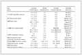
Wheat straw was first broken into about 3 mm size and then dried for use. The C, H, N and S elements of the sample were determined by FLASH2000 elemental analysis instrument (air drying base), and the content of O elements was determined by the difference method. Industrial analysis adopts GB/T 28731—2012 industrial analysis method for solid biomass fuel. The results are shown in Table 1.
Table 1
 下载:
导出CSV
下载:
导出CSV
Ultimate analysis w/% Proximate analysis w/% C H O N S M A V FC 33.65 4.91 51.88 0.89 0.15 11.15 8.43 78.1 2.69 1.2 Catalyst preparation
Firstly, the tire pyrolysis char (TPC) was broken, sealed and soaked in 5mol/L hydrochloric acid solution, and filtered, washed and dried. Secondly, certain proportion of Ni (NO3)2·6H2O and treated TPC were added in a 250mL flask, and then 40g urea and 150mL deionized water were added. The sample was heated 2h at 115℃. Finally, after filtering, washing, drying in vacuum, and heat preservation for 3h in N2 atmosphere under 850℃, Ni/TPC catalyst was synthesized.
1.3 Characterization of catalyst
The element composition and material structure of the catalyst were tested by EDX-7000 X-ray fluorescence spectrometer (EDX) and X-ray diffractometer (XRD). The surface morphology of catalyst particles was observed by S-3000N scanning electron microscope (SEM). The surface area was analyzed by Autosorb-l-c automatic chemical adsorption instrument. The thermal stability of the catalyst was evaluated using the Q600 heat retest instrument (TG/DTG).
1.4 Evaluation of catalytic activity
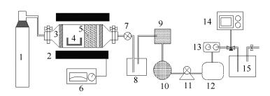
The activity of Ni/TPC catalyst was tested in a fixed pyrolysis furnace shown in Figure 1. The porcelain boat with wheat straw and catalyst bed were fed into the pyrolysis furnace through the flange mouth before the trial. The high-purity nitrogen was used to exclude the furnace tube air. The reactor temperature was programmed to the set value and preserved a certain period. The evolution gases were analyzed by Gasboard-3100P infrared gas analyzer.
Figure 1
 Figure 1. Flow scheme of bench scale reactor for catalytic pyrolysis of straws biomass
1: nitrogen; 2: pyrolysis gasifier and thermocouples; 3: insulation brick; 4: porcelain boat; 5: catalytic bed and catalyst; 6: temperature controller; 7: waterproof valve; 8: water channel; 9: particle filter; 10: gas dryer (silica gel); 11: pump; 12: gas buffer package; 13: flowmeter; 14: gas analyzer; 15: fire prevention
2. Results and discussion
2.1 Characterization of Ni catalysts
2.1.1 EDX analysis
The components of TPC, Ni/TPC and wasted Ni/TPC were analyzed and shown in Table 2. It can be seen that the carrier TPC is mainly composed of C, S, Zn, Si, Ca, K and Fe. The Ni content in the fresh Ni/TPC catalyst was 28.44% which was close to the theoretical load of 30%. The Ni was 27.91% in the waste Ni/TPC catalyst after 850min reaction. Compared with the fresh Ni/TPC catalyst, Ni and other metal contents of the waste Ni/TPC catalyst were decreased. The increase of C content in the waste catalyst was caused by carbon deposition on the surface of the catalyst[21, 22].
Table 2
Table 2. EDX element analysis of three samples下载:
导出CSV
Sample Main composition and content w/% Ni C S Zn Si Ca Fe K TPC - 61.49 15.47 13.94 5.85 1.16 0.93 0.73 30% Ni/TPC 28.44 42.81 11.25 10.46 4.66 0.86 0.71 0.54 Waste Ni/TPC 27.91 43.75 11.44 9.96 4.61 0.82 0.65 0.55 2.1.2 XRD analysis
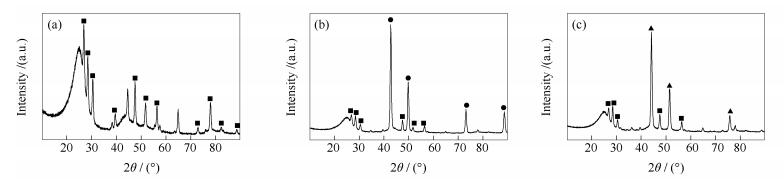
Figure 2 shows the XRD spectra of TPC, Ni/TPC and waste Ni/TPC. Besides the characteristic peaks of ZnS (PDF2004/36-1450), there are also some others for the TPC. For the Ni/TPC catalyst the peaks in 42.76°, 49.78°, 73.14° and 88.62° are mainly the characteristic peak of Ni3ZnC0.7 (PDF2004/28-0713). Previous research showed that Ni active component was present in the form of Ni3ZnC0.7 in the Ni/TPC catalyst[23]. For the waste Ni/TPC catalyst there isn't Ni3ZnC0.7 structure, and peaks in 44.16°, 51.46° and 75.82° are mainly the characteristic peak of FeNi3 (PDF2004/38-0419). It shows that the active component structure of Ni/TPC catalyst was converted after repeatedly used[24].
Figure 2
 Figure 2. XRD patterns of TPC and Ni/TPC and waste Ni/TPC
(a): TPC; (b): Ni/TPC; (c): waste Ni/TPC
■: ZnS; ●: Ni3ZnC0.7; ▲: FeNi32.1.3 SEM analysis
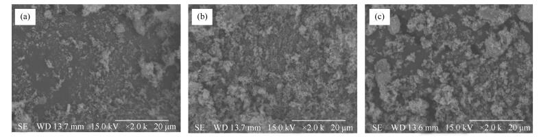
Figure 3 shows the SEM images of TPC, Ni/TPC and waste Ni/TPC. For the carrier TPC particles are scattered and the particles size is not uniform and regular distribution. For the Ni/TPC catalyst the particles are fluffy like a piece of sponge. Some particles of waste Ni/TPC catalyst become unevenly. There is the deposition carbon in the surface of Ni/TPC catalyst because of the repeated use of the catalyst[25].
Figure 3
 Figure 3. SEM images of TPC, Ni/TPC and waste Ni/TPC
(a): TPC; (b): Ni/TPC; (c): waste Ni/TPC
2.1.4 TG analysis
Figure 4 shows the TG/DTG curves of Ni/TPC catalyst and wheat straw. The pyrolysis process of wheat straw is mainly divided into three stages. The wheat straw begins to dehydration at 30℃ and its physical water is completely lost at blow 160℃ in region 1, which is physical dehydration and drying stage[26]. Region 2 from 160 to 550℃ is mainly the devolatilization stage, and the wheat straw begins to devolatilize and decompose into gas, carbon and tar shown in equation (1)[27]. The maximum weight loss peak is at 320℃ with weight loss rate of 7.1%/℃. Region 3 is the secondary pyrolytic cracking stage. There were homogeneous reactions (between the gas and steam) and heterogeneous reactions (between char and gas and steam) in this stage with the main reactions of equation (2)-(6)[28, 29].
Figure 4
Meanwhile, with the temperature increase, the quality of the catalyst has few changes from the TG curve of Ni/TPC catalyst, which indicates that the thermal stability of Ni/TPC catalyst is excellent[30].
$ {{\rm{C}}_x}{{\rm{H}}_y}{{\rm{O}}_z} \to {{\rm{H}}_{\rm{2}}}{\rm{ + CO + C}}{{\rm{O}}_{\rm{2}}}{\rm{ + }}{{\rm{H}}_{\rm{2}}}{\rm{O + C}}{{\rm{H}}_{\rm{4}}}{\rm{ + C + }}{{\rm{C}}_m}{{\rm{H}}_{n}} $
(1) $ {\rm{C + }}{{\rm{H}}_{\rm{2}}}{\rm{O }} \to {\rm{ CO + }}{{\rm{H}}_{{\rm{2}}}} $
(2) $ {\rm{CO + }}{{\rm{H}}_{\rm{2}}}{\rm{O }} \to {\rm{ C}}{{\rm{O}}_{{\rm{2}}}}{\rm{ + }}{{\rm{H}}_{\rm{2}}} $
(3) $ {\rm{C + 2}}{{\rm{H}}_{{\rm{2}}}} \to {\rm{C}}{{\rm{H}}_{{\rm{4}}}} $
(4) $ {\rm{C + C}}{{\rm{O}}_{{\rm{2}}}} \to {\rm{ 2CO}} $
(5) $ {\rm{C}}{{\rm{H}}_{\rm{4}}}{\rm{ + }}{{\rm{H}}_{\rm{2}}}{\rm{O }} \to {\rm{CO + 3}}{{\rm{H}}_{\rm{2}}} $
(6) 2.1.5 BET analysis
Table 3 shows the BET surface area of TPC and Ni/TPC and waste Ni/TPC. The BET surface area of the carrier TPC is 84m2/g, the Ni/TPC catalyst is 62m2/g, and the waste Ni/TPC catalyst is 49m2/g. The BET surface area decrease of Ni/TPC catalyst is mainly caused by the load of active component[31]. The BET surface area decrease of waste Ni/TPC catalyst is mainly caused by the deposition of carbon in the reaction[32].
Table 3
Table 3. BET surface area of TPC and Ni/TPC waste Ni/TPC下载:
导出CSV
Sample TPC Ni/TPC Waste Ni/TPC BET surface area A/(m2·g-1) 84 62 49 2.2 Catalytic performance of Ni/TPC catalyst
The wheat straw sample with or without TPC or Ni/TPC catalyst were put in biomass pyrolysis reactor, and the experiments were carried out under the same condition. The catalytic activity of Ni/TPC in wheat straw pyrolysis was evaluated by comparing H2 and CO content in gas. Meanwhile, the performance of Ni/TPC catalyst including reforming temperature, holding time, Ni loading and use time on the straw pyrolysis was investigated.
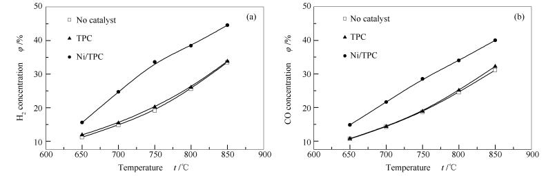
2.2.1 Effect of reforming temperature
Figure 5 shows the influence of pyrolysis temperature on wheat straw pyrolysis gas production. As the pyrolysis temperature increase, the contents of H2 and CO also increase. The H2 and CO gas productions are almost the same for TPC catalyst and without catalyst, which indicates that the TPC does not have catalytic activity in wheat straw pyrolysis. When use Ni/TPC catalyst the contents of H2 and CO are significantly high, which shows that Ni/TPC catalyst has a remarkable catalytic effect in pyrolysis of wheat straw.
Figure 5
Compared the gas products at 750℃ with or without Ni catalyst, the H2 gas content increases from 19% to 33.6%, and the CO gas content increases from 18.5% to 28.6%. The relative improvements of H2 and CO contents are the highest compared with other pyrolysis temperature. So the catalytic efficiency of Ni/TPC catalyst is highest at the pyrolysis temperature of 750℃, and 750℃ was chosen as the following reaction temperature.
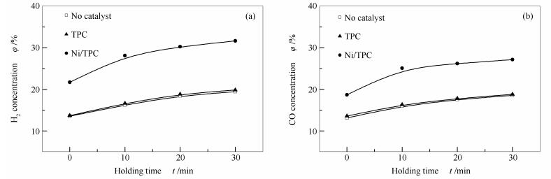
2.2.2 Effect of holding time
Figure 6 shows the influence of different holding time on wheat straw pyrolysis gas production. With the holding time increase, the H2 and CO contents also increase. When the holding time is more than 10min the H2 and CO increase slowly. When the holding time is 10min for Ni/TPC catalyst, the content of H2 gas increases from 16.2% to 28.2%, and the CO gas content increases from 16% to 26%. So the holding time of 10min was chosen as Ni/TPC catalyst had highest products increment. When the holding time is increased, the contact time between the tar macromolecule and the catalyst is prolonged, and the catalytic reaction time is also increased, so the catalytic reaction will be increased. However, when the holding time exceeds 20min, most of the tar molecules have already been decomposed, the continue increase of holding time will not improve the gas product significantly.
Figure 6
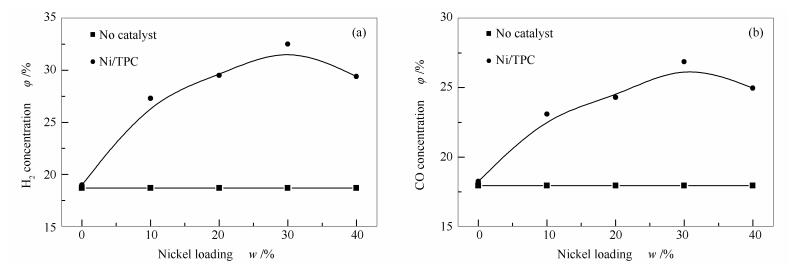
2.2.3 Effect of Ni loading
Figure 7 shows the influence of different Ni load of Ni/TPC catalyst on wheat straw pyrolysis gas production.
Figure 7
As the nickel loading increases the contents of H2 and CO are first increase and then decrease. When the Ni loading is 30%, the H2 content increases from 18.5% to 32.5%, and the CO content increases from 18% to 27%. When the nickel loading is 30%, the Ni/TPC catalyst has highest catalytic efficiency in wheat straw pyrolysis. When the Ni loading is too high, a large amount of Ni enters to the carrier pores, clogs the pores of the carrier, and the active components inside the catalyst particles cannot contact the tar macromolecules resulting in a decrease in the catalytic reforming activity[33].
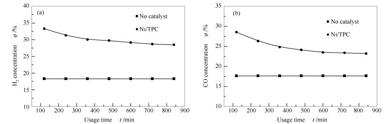
2.2.4 Effect of usage time
Figure 8 shows the influence of different reaction time of the Ni/TPC on wheat straw pyrolysis gas production.
Figure 8
With the increase of using time the H2 and CO gas contents slowly decrease. The contents of H2 and CO are gradually stable after 600min. According to the XRD pattern of Figure 2, the active component Ni3ZnC0.7 changes to FeNi3 after the catalyst is used. Therefore, it is considered that the decrease of the catalytic activity after long-term use is due to the change of the active component, and the catalytic performance of Ni3ZnC0.7 is higher than that of FeNi3.
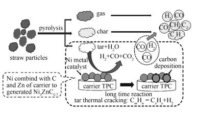
2.2.5 Thermal catalytic process analysis
The catalytic pyrolysis of wheat straw process is shown in Figure 9.
Figure 9
The tar macromolecules and water vapor contact at the surface of the Ni/TPC catalyst, and some tar macromolecules are catalytic split into small molecular gases such as hydrogen and carbon monoxide. At the same time, the other tar macromolecules which do not contact with the catalyst are also thermally cracked into lighter, smaller molecular tar and H2 [34]. During the tar macromolecules reforming reactions and cracking reactions, carbon deposition on the catalyst surface can occur and cause the decrease of the catalytic activity. After a long period use, the active component Ni3ZnC0.7 can change and convert to the FeNi3 structure. Through the long time experimental data, it is found that FeNi3 also has relative strong reforming catalytic activity and can be used for a long reforming reaction period.
3. Conclusions
The results show that Ni loaded on TPC with a specific surface area of 62m2/g has strong catalytic activity for wheat straw pyrolysis gas reforming. Meanwhile, nickel combines with Zn and C species in the carrier to form Ni3ZnC0.7 structure. The active components of Ni3ZnC0.7 is changed to FeNi3 after long-term used.
The Ni/TPC catalyst has the highest catalytic efficiency at 750℃ with a 10min holding time and 30% Ni loading. The content of H2 is still higher after continuous use of 850min.
-
-
[1]
STIEGEL G J, MAXWELL R C. Gasification technologies:The path to clean, affordable energy in the 21st century[J]. Fuel Process Technol, 2001, 71(1/3): 79-97.
-
[2]
WALTERTORRES , PANSARE S, GOODWINJR J. Hot gas removal of tars, ammonia, and hydrogen sulfide from biomass gasification gas[J]. Catal Rev, 2007, 49(4): 407-456. doi: 10.1080/01614940701375134
-
[3]
NAZEMI M, PADGETT J, HATZELL M C. Acid/base multi-ion exchange membrane-based electrolysis system for water splitting[J]. Energy Technol, 2017, : .
-
[4]
PALO D R, AND R A D, HOLLADAY J D. Methanol steam reforming for hydrogen production[J]. Chem Rev, 2007, 107(10): 3992. doi: 10.1021/cr050198b
-
[5]
BULUSHEV D A, ROSS J R H. Catalysis for conversion of biomass to fuels via pyrolysis and gasification:A review[J]. Cataly Today, 2011, 171(1): 1-13. doi: 10.1016/j.cattod.2011.02.005
-
[6]
GARC A-D EZ E, GARC A-LABIANO F, DIEGO L F D, ABAD A, GAYÁN P, ADÁNEZ J. Autothermal chemical looping reforming process of different fossil liquid fuels[J]. Int J Hydrogen Energy, 2017, 42(19): 13633-13640. doi: 10.1016/j.ijhydene.2016.12.109
-
[7]
BRIDGWATER A V. The technical and economic feasibility of biomass gasification for power generation[J]. Fuel, 1995, 74(5): 631-653. doi: 10.1016/0016-2361(95)00001-L
-
[8]
HAN J, KIM H. The reduction and control technology of tar during biomass gasification/pyrolysis:An overview[J]. Renewable Sustainable Energy Rev, 2008, 12(2): 397-416. doi: 10.1016/j.rser.2006.07.015
-
[9]
HUBER G W, IBORRA S, CORMA A. Synthesis of transportation fuels from biomass:Chemistry, catalysts, and engineering[J]. Chem Rev, 2006, 106(9): 4044-4098. doi: 10.1021/cr068360d
-
[10]
HE M, XIAO B, HU Z, LIU S M, GUO X J, LUO S Y. Syngas production from catalytic gasification of waste polyethylene:Influence of temperature on gas yield and composition[J]. Int J Hydrogen Energy, 2009, 34(3): 1342-1348. doi: 10.1016/j.ijhydene.2008.12.023
-
[11]
YU Q Z, BRAGE C, NORDGREEN T, SJÖSTRÖM K. Effects of Chinese dolomites on tar cracking in gasification of birch[J]. Fuel, 2009, 88(10): 1922-1926. doi: 10.1016/j.fuel.2009.04.020
-
[12]
FURUSAWA T, TSUTSUMI A. Comparison of Co/MgO and Ni/MgO catalysts for the steam reforming of naphthalene as a model compound of tar derived from biomass gasification[J]. Appl Catal A:Gen, 2005, 278(2): 207-212. doi: 10.1016/j.apcata.2004.09.035
-
[13]
WANG D, YUAN W, JI W. Use of biomass hydrothermal conversion char as the Ni catalyst support in benzene and gasification tar removal[J]. Trans ASABE, 2010, 53(3): 795-800. doi: 10.13031/2013.30053
-
[14]
CHOI Y K, CHO M H, KIM J S, LUND H, KAISER M J. Steam/oxygen gasification of dried sewage sludge in a two-stage gasifier:Effects of the steam to fuel ratio and ash of the activated carbon on the production of hydrogen and tar removal[J]. Energy, 2015, 91(suppl 2): 160-167.
-
[15]
DUC L D, XIAO X, MORISHITA K, TAKARADA T. Biomass gasification using nickel loaded brown coal char in fluidized bed gasifier at relatively low temperature[J]. J Chem Eng Jpn, 2009, 42(1): 51-57. doi: 10.1252/jcej.08we218
-
[16]
WANG T J, CHEN Y WU C Z, FU Y, CHANG J. The steam reforming of naphthalene over a nickel-dolomite cracking catalyst[J]. Biomass Bioenergy, 2005, 28(5): 508-514. doi: 10.1016/j.biombioe.2004.11.006
-
[17]
WANG D, YUAN W, JI W. Char and char-supported nickel catalysts for secondary syngas cleanup and conditioning[J]. Appl Energy, 2011, 88(5): 1656-1663. doi: 10.1016/j.apenergy.2010.11.041
-
[18]
SHEN Y, ZHAO P, SHAO Q, MA D C, TAKAHASHI F, YOSHIKAWA K. In-situ catalytic conversion of tar using rice husk char-supported nickel-iron catalysts for biomass pyrolysis/gasification[J]. Appl Catal B:Environ, 2014, s152/153(1): 140-151.
-
[19]
MIN Z, ASADULLAH M, YIMSIRI P, SHU Z, WU H W, CHUN Z L. Catalytic reforming of tar during gasification. Part Ⅰ. Steam reforming of biomass tar using ilmenite as a catalyst[J]. Fuel, 2011, 90(5): 1847-1854. doi: 10.1016/j.fuel.2010.12.039
-
[20]
ALRAHBI A S, WILLIAMS P T, YAN J. Hydrogen-rich syngas production and tar removal from biomass gasification using sacrificial tire pyrolysis char[J]. Appl Energy, 2017, 190: 501-509. doi: 10.1016/j.apenergy.2016.12.099
-
[21]
BAE K W. The role of carbon deposition in the gas phase transesterification of dimethylcarbonate and phenol over TiO2/SiO2 catalyst[J]. Appl Catal A:Gen, 2015, 194(1): 403-414.
-
[22]
QIAN K, KUMAR A. Catalytic reforming of toluene and naphthalene (model tar) by char supported nickel catalyst[J]. Fuel, 2017, 187: 128-136. doi: 10.1016/j.fuel.2016.09.043
-
[23]
ZHAO Y, LI X, LIU J, WANG C, ZHAO Y. MOF-Derived ZnO/Ni3ZnC0.7/C Hybrids Yolk-Shell microspheres with excellent electrochemical performances for lithium ion batteries[J]. Acs Appl Mater Inter, 2016, 8(10): 6472-6480. doi: 10.1021/acsami.5b12562
-
[24]
WANG Y, JIANG L, HU S, SU S, ZHOU Y B, XIANG J, ZHANG S, CHUN Z L. Evolution of structure and activity of char-supported iron catalysts prepared for steam reforming of bio-oil[J]. Fuel Process Technol, 2017, 158: 180-190. doi: 10.1016/j.fuproc.2017.01.002
-
[25]
LIU X, XIONG B, HUANG X, DING H R, ZHENGY , LIU Z H, ZHENG C G. Effect of catalysts on char structural evolution during hydrogasification under high pressure[J]. Fuel, 2017, 188(2): 474-482.
-
[26]
BRIDGWATER A V. Renewable fuels and chemicals by thermal processing of biomass[J]. Chem Eng J, 2003, 91(2): 87-102.
-
[27]
BRIDGWATER A, GERHAUSER H, EFFENDI A. Biomass pyrolysis process: Australia, 2074192[P]. 2014-05-07.
-
[28]
NEGRO M J, MANZANARES P, OLIVA J M, BALLESTEROS I, BALLESTEROS M. Changes in various physical/chemical parameters of Pinus pinaster wood after steam explosion pretreatment[J]. Biomass Bioenergy, 2003, 25(3): 301-308. doi: 10.1016/S0961-9534(03)00017-5
-
[29]
TABA L E, IRFAN M F, WAN A M W D, CHAKRABARTI M H. The effect of temperature on various parameters in coal, biomass and CO-gasification:A review[J]. Renewable Sustainable Energy Rev, 2012, 16(8): 5584-5596. doi: 10.1016/j.rser.2012.06.015
-
[30]
ANTONAKOU E, DIMITROPOULOS V, LAPPAS A. Production and characterization of bio-oil from catalytic biomass pyrolysis[J]. Therm Sci, 2014, 10(3): 151-160.
-
[31]
DONALD J, XU C, HASHIMOTO H, BYAMBAJAV E, OHTSUKA Y. Novel carbon-based Ni/Fe catalysts derived from peat for hot gas ammonia decomposition in an inert helium atmosphere[J]. Appl Catal A:Gen, 2010, 375(1): 124-133. doi: 10.1016/j.apcata.2009.12.030
-
[32]
ARKATOVA L A. The deposition of coke during carbon dioxide reforming of methane over intermetallides[J]. Catal Today, 2010, 157(1/4): 170-176.
-
[33]
XU L, SONG H, CHOU L. Carbon dioxide reforming of methane over ordered mesoporous NiO-MgO-Al2O3 composite oxides[J]. Appl Catal B:Environ, 2011, s108/109(6): 177-190.
-
[34]
ZHAO B F, ZHANG X D, LEI C, QU R B, MENG G F, YI X L, LI S. Steam reforming of toluene as model compound of biomass pyrolysis tar for hydrogen[J]. Biomass Bioenergy, 2010, 34(1): 140-144. doi: 10.1016/j.biombioe.2009.10.011
-
[1]
-
Figure 1 Flow scheme of bench scale reactor for catalytic pyrolysis of straws biomass
1: nitrogen; 2: pyrolysis gasifier and thermocouples; 3: insulation brick; 4: porcelain boat; 5: catalytic bed and catalyst; 6: temperature controller; 7: waterproof valve; 8: water channel; 9: particle filter; 10: gas dryer (silica gel); 11: pump; 12: gas buffer package; 13: flowmeter; 14: gas analyzer; 15: fire prevention
Figure 2 XRD patterns of TPC and Ni/TPC and waste Ni/TPC
(a): TPC; (b): Ni/TPC; (c): waste Ni/TPC
■: ZnS; ●: Ni3ZnC0.7; ▲: FeNi3
Figure 3 SEM images of TPC, Ni/TPC and waste Ni/TPC
(a): TPC; (b): Ni/TPC; (c): waste Ni/TPC
Table 1. Ultimate and proximate analyses of wheat straw sample
Ultimate analysis w/% Proximate analysis w/% C H O N S M A V FC 33.65 4.91 51.88 0.89 0.15 11.15 8.43 78.1 2.69  下载: 导出CSV
Table 2. EDX element analysis of three samples
Sample Main composition and content w/% Ni C S Zn Si Ca Fe K TPC - 61.49 15.47 13.94 5.85 1.16 0.93 0.73 30% Ni/TPC 28.44 42.81 11.25 10.46 4.66 0.86 0.71 0.54 Waste Ni/TPC 27.91 43.75 11.44 9.96 4.61 0.82 0.65 0.55
下载: 导出CSV
Table 3. BET surface area of TPC and Ni/TPC waste Ni/TPC
Sample TPC Ni/TPC Waste Ni/TPC BET surface area A/(m2·g-1) 84 62 49
下载: 导出CSV
-


 扫一扫看文章
计量
- PDF下载量: 0
- 文章访问数: 0
- HTML全文浏览量: 0
