

 Table 1.
Properties of heavy vacuum gas oil feedstock
Table 1.
Properties of heavy vacuum gas oil feedstock
Citation:
Ahmed W., Ahmed Hoda, S., El-Sheshtawy H.S., Mohamed Nadia, A., Zahran Asmaa, I.. Egyptian heavy vacuum gas oil hydrotreating over Co-Mo/CNT and Co-Mo/γ-Al2O3 catalysts[J]. Journal of Fuel Chemistry and Technology,
2016, 44(7): 853-861.

Egyptian heavy vacuum gas oil hydrotreating over Co-Mo/CNT and Co-Mo/γ-Al2O3 catalysts
English
Egyptian heavy vacuum gas oil hydrotreating over Co-Mo/CNT and Co-Mo/γ-Al2O3 catalysts
Abstract:
The catalytic activity of CoMoS/CNT towards the Egyptian heavy vacuum gas oil hydrotreating was studied. The delivered CNT was functionalized with 6 mol/L HNO3. The CNT were loaded with 12% MoO3 (by weight) and 0.7 Co/Mo atomic ratio with impregnation methods. The γ-Al2O3catalyst was also prepared by impregnation method to compare both catalysts activities. The analysis tools such XRD, Raman spectroscopy, TEM, and BET were used to characterize the catalysts. The autoclave reactor was used to operate the hydrotreating experiments. The hydrotreating reactions were tested at various operating conditions of temperature 325-375 ℃, pressure 2-6 MPa, time 2-6 h, and catalyst/oil ratio (by weight) of 1:75, 1:33 and 1:10. The results revealed that the CoMoS/CNT was highly efficient for the hydrotreating more than the CoMoS/γ-Al2O3. Also, the hydrodesulfurization (HDS) increased with increasing catalyst/oil ratio. Additionally, results showed that the optimum condition was temperature 350 ℃, pressure 4 MPa, catalyst/oil ratio of 1:75 for 2 h. Furthermore, even at low CoMoS/CNT catalyst/oil ratio of 1:75, an acceptable HDS of 77.1% was achieved.
-
Key words:
- hydrotreatment
- / hydrodesulfurization
- / carbon nanotube
- / heavy vacuum gas oil (HVGO)
-
Because of economical and pollution control aspects, up the year 2010, the international low limit of the sulfur content in fuels is to < 1.5×10⁻⁵[1-4]. For such propos, enormous effects have been done to develop the hydrotreatment process, responsible for S and N removal. Commonly, the MoS promoted by Co or Ni active phases supported on γ-Al2O3 is the most active hydrotreating catalyst[5, 6]. The Co-Mo based catalyst is highly selective for HDS while Ni-Mo based catalyst is known as selective for hydrodenitrogenation (HDN). So that, Ni-Mo catalysts has the drawback of consuming higher hydrogen than Co-Mo based catalysts for HDS process with identical feed[7].
Although the γ-Al2O3 support has good thermal, textural properties and high metal dispersion ability[8], it strongly interacts with the active metal[9]. This interaction hinder the complete metals sulfidation which decreases the required active sites[10]. Nevertheless, this drawback motivates the researchers to suggest another supports to Co-Mo catalysts for hydrotreating[9, 11-14].
Among many supports carbon nanotube (CNT) is an attractive alternative support. It possesses the advantages of high thermal, mechanical strength and high surface area as γ-Al2O3, and also other unique properties such as excellent electron transporting capability[15]. So, it is used as catalyst support for many reactions[16, 17]. It has a high surface area with controlled pore volume and pore size which reduce the carbon deposition and provide enough surface for metal dispersion[18]. Unlike alumina, the CNT hydrophobic surface limits the metal support interaction which facilitates the metal sulfidation process. Additionally, the acid treatment of CNT creates OH- or COO- functional groups that enhance the Co and Mo dispersion[19, 20].
Dong et al[21] reported that an appreciable active MoO2species were formation in Co-Mo/CNT catalyst and HDS activity was enhanced. Shang et al[22] reported a considerable higher selectivity of Co-Mo/CNTs catalyst than Al2O3-based catalyst. This observation was attributed to the formation of MoO2 species rather than MoO3 formed over alumina support. Furthermore, it is also concluded that the highest catalytic performance can be achieved over the catalyst with 0.7 Co/Mo atomic ratio.
Despite number of reports on Co-Mo/CNT for HDS were explored, there are no reports on the hydrotreating of Egyptian heavy vacuum gas oil (HVGO). Also there are rare researches in Co-Mo/CNT catalyst to feed ratio effect on the hydrotreating.
Considering the above argument, this study investigated the Co-Mo/CNT catalytic activity toward the Egyptian HVGO hydrotreatment. In addition, the hydrotreating experimental conditions were optimized. For more convenient the catalytic performance was compared to the conventional Co-Mo/γ-Al2O3 catalyst.
1 Experimental
1.1 Feedstock
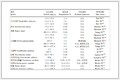
Heavy vacuum gas oil (HVGO) feedstock in this study was purchased from Suez Oil Petroleum Company (SOPC). The main characteristics of the feedstock are indicated in Table 1.
Table 1.
Properties of heavy vacuum gas oil feedstock
Experiment Method Result Total sulfur content w/% ASTM D-4294 1.66 Aniline point /°F ASTM D-611-82 74 Diesel index /% ASTM D 611 46.09 Total aromatics w/% - 34 Table 1. Properties of heavy vacuum gas oil feedstock1.2 Catalyst preparation
1.3 Catalyst characterization
1.4 Catalytic activity test
The catalysts were presulfied prior to the activity tests (i.e. hydrotreating), in the autoclave at the following conditions: 1.5 MPa initial hydrogen pressure, 350 ℃ reaction temperature and 5 h reaction period. For this purpose, 8% (of the catalyst weight) dimethyldisulfide (DMDS) was used as sulfiding agent in light gas oil diluent.
The sulfided catalyst is transferred out and kept in a vacuum environment to avoid contact with air till usage. The hydrotreating experiments were carried out in a static phase using batch reactor (parr.model 7575). The reactor temperature and stirring were electrically controlled, while the pressure was controlled manually. A 150 g feed and 2 g of the sulfided catalyst were loaded inside the reactor. After tightly closing the reactor, reactant and catalyst was purged in N2 in order to check the pressure leakage. The hydrotreatment operation conditions of temperature (325-375 ℃), initial pressure (2-6 MPa), time (2-6 h) and catalyst to feed ratio of 1:75, 1:33 and 1:10 (g/g) were individually set in.
After the required temperature, pressure and a constant catalyst/oil ratio were reached, the experiment was conducted for the desired time. Afterwards, the autoclave was maintained to cool to room temperature overnight. The Liquid products were purged out of the autoclave under sufficient N2-pressure, and collected for analysis using the recommended standard methods (i.e. ASTM or IP methods). The catalyst was filtered and washed by solvent (naphtha). The filtered catalyst was heated in an electric oven at 110 ℃ for 2 h.
1.2.2 Co-Mo loading
Ammonium heptamolybdate tetrahydrate and cobalt acetate precursors were used for molybdenum and cobalt preparation respectively. The pore volume impregnation method was used to prepare the catalyst with 12% MoO3 loading and Co/Mo atomic ratio of 0.7. The impregnation was carried out in two stages to avoid the precipitation of catalyst metal from the saturated solution. Firstly, the Mo species was loaded by dissolving the required weight of ammonium heptamolybdate tetrahydrate in an estimated doubly distilled water volume with a few H2O2 droplets to give a transparent solution. The solution was added to the needed CNT amount and stirred for 30 min. After impregnation, the formed moist paste was preliminary dried in an oven at 120 ℃ over night. The dried samples were calcined in a muffle furnace with a heating rate of 10 ℃/min up to 400 ℃ for 4 h. Afterwards, the Co precursor introduced by pore volume impregnation, followed by drying at 120 ℃ over night. Finally the bimetallic catalysts were calcined at 400 ℃ in a muffle furnace for 4 h.
For alumina supported catalyst, the same procedures were used to deposit the Mo and Co over the alumina at the same drying and calcination conditions.
1.2.1 Synthesis and purification of carbon nanotube
Carbon nanotube were prepared by CVD method and kindly supplied by Awadallah research group (at Egyptian petroleum research institute)[23]. The CNT were purified and functionalized with 6 mol/L HNO3 and then stirred for 4 h. Then it was filtered and washed by doubly distilled water several times, followed by drying at 120 ℃ overnight.
1.3.1 X-ray diffraction
The catalysts formed phases were determined by the X-ray diffraction analysis using X’Pert PRO PANalytical apparatus. The patterns were recorded using Cu Kα radiation (λ=0.154 18 nm). The 2θ ranges from 10° to 70° at a scanning rate of 0.05 s-1 were used to record the patterns.
1.3.3 Raman spectroscopy
Raman spectra of the as-grown carbon nanotube and Co-Mo/CNT samples were recorded by SENTERRA Dispersive Raman Microscope (Bruker). The apparatus was equipped with a diode Nd:YAG laser and wave length of 532 nm. The experiments were carried out at room temperature in range of 10 to 2 000 cm-1.
1.3.2 Transmission electron microscopy
The CNT and Co-Mo/CNT catalysts morphology were determined using a JEOL 2010F TEM apparatus. An accelerating voltage of 200 kV was used to obtain the images. Before measurements, the samples suspensions were prepared with 5 mL ethanol. The mixture was sonicated for 20 min then a solution droplet was placed on the Cu grid. The ethanol was then slowly evaporated in open air from the Cu grid under a glass cover.
1.3.4 Surface area measurement
The prepared catalyst physico-chemical properties were determined by N2 adsorption-desorption method at -196 ℃. The Autosorb 1, Quanta chrome instrument was used to measure the BET surface area. Prior to the measurement, the adsorbed gases and moisture had removed by the samples degassing at 200 ℃ for 4 h. Surface area was calculated using the adsorption data up to a relative pressure of 0.1 by BET method.
2 Result and discussion
2.1 X-ray diffraction
The XRD patterns of functionalized CNT and supported catalysts after calcination are demonstrated in Figure 1. The pure functionalized CNT shows (Figure 1a) peaks at 2θ of 26.05° and 43.08° which are ascribed to the (002) graphitic basal plane and (100) plane respectively[22, 24, 25]. This observation indicates the low graphitization degree of CNT used in this study. The results may generally be responsible for catalyst’s high surface area[26].
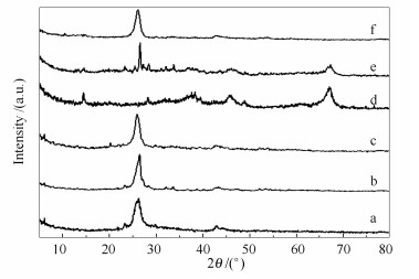 Figure 1.
XRD patterns of different samples
Figure 1.
XRD patterns of different samples
The XRD spectrum of the γ-Al2O3 (Figure 1d) shows broad diffraction peaks at 2θ=37.5°, 45.7° and 67.1° which are related to crystal phase of γ-Al2O3[22].
The XRD patterns of Co-Mo loaded CNT and S-Mo/CNT are illustrated in Figure 1b and 1c respectively. The intensities of CNT main peaks are declined by metals loading. Tan et al[27] attributed this patterns decrease to the change in ordered structure because of metals loading.
Figure 1b shows diffraction peaks at 2θ of 26.18° and 36.98°, which are characteristics for MoO2 for the Mo loaded CNT catalyst[22, 28]. Furthermore, very low intensity peaks for MoO3 crystalline phase are measured. The presence of MoO3 weak peaks may be attributed to slightly incomplete acidification of some CNT surface and hence lower functional groups[9]. These observations reflect basically the presence of low valence Mo species on the CNT surface. This may be explained by the weak metal-support interaction due to the CNTs surface hydrophobicty[29]. The weak metal-support interaction helps the MoO3 to migrate and conglomerate on the CNTs surface. So, the Mo species are reduced into the lower valence state during the calcination. The same observations are also claimed previously[22, 25, 30].
In contrary, by Mo loading on alumina (Figure 1e) diffraction lines at 2θ of 27.3°, 25.7° and 23.3° which are attributed to the (021), (040) and (110) crystallographic planes of the orthorhombic MoO3 phase are observed. The XRD results indicate that no new compounds are formed suggesting that the reaction between MoO3 and γ-Al2O3 does not occur during treatment in air at 450 ℃. The CoMoO4 diffraction peaks at 2θ=13.2°, 19.1°, 23.3°, 25.5°, 26.5°, 32.0° and 33.7° can be found. This is explained by partial Co to Mo interaction during the drying processes.
Also, a very tiny peak at 49°, but not peaks at 31.7° and 59.6°, attributed to CoAl2O4 in the XRD pattern of Mo-Co/Al catalyst, is observed. This result indicates a very weak Co-Al2O3 interaction which can be explained in two bases. One reason is that the almost γ-Al2O3 surface saturation with MoO3. On the other hand, Mo-Co interaction may have a synergistic effect than contact the γ-Al2O3.
Figure 1c shows the XRD patterns of sulfided Co-Mo/CNT. The figure demonstrates that neither Co3O4 nor its sulfide phases are detected. In contrary, Weak broad peaks at 14.4° and 32.71° which are attribute to (002) and (100) planes of MoS2 are assigned. Moreover, a weak peak at 29.0° due to the low valence Co-MoS3.13 or Co-MoS2.17 species formation is assigned[22]. Also, figure shows lower molybdenum oxide species peaks intensity. This may be due to the Co atoms incorporation in the MoO3 crystals and limiting their growth. It may be concluded that the cobalt loading and the sulfiding process emphasizes the active phase's dispersion on the CNT.
In contrary of CNT supported catalyst, the sulfided Co-MoS/γ-Al2O3 catalyst shows a completely different XRD spectrum than the oxidic catalyst. The XRD spectrum of sulfided catalyst (Figure 1f) shows the peaks neither related to the γ-Al2O3 nor Co and Mo interactions. These results may be concluded that the cobalt loading and the sulfiding process emphasizes MoO3 dispersion in alumina.
Furthermore, only a broad high intense peak at 26.5° attributed to the MoO3 species is recorded. This may confirm the well dispersion of the Co species on the Mo surface layer over alumina surface. The presence of broad Mo species peak proves its small particle size. Additionally, the peaks corresponding to the Mo3S4 crystallite formation at 14.4° and 32.71° are not assigned. Also, the peaks for molybdenum oxide species intensity are disappeared.
Considering the Co species, neither Co3O4 nor the sulfide Co species in the Co-MoS/γ-Al2O3 XRD spectrum are observed. These results also confirm the well dispersed Co species in MoS2.
2.2 Transmission electron microscopy (TEM)
Figure 2 shows the TEM images of the pure CNT and S-CoMo/CNT catalyst. The TEM image Figure 2(a) shows the uniform diameter CNT morphological properties. It reveals that the nanotubes have 20 nm average outer diameters and about 10 nm wall thickness. Figure 2(b) illustrates the TEM images of the S-Co-Mo/CNT catalyst. The images demonstrate good metals dispersed over CNT support. This observation confirms the data obtained from XRD. Additionally, no noticeable Mo species agglomeration is observed. Furthermore, no Co metals inside the CNTs are detected. These results may be related to the CNT inner diameter and its functional groups. Comparing Figure 2(a) and 2(b), it’s obvious that the function groups on CNT act as anchoring sites that prevent the cobalt particles immigration into the tubes and the particles sintering by calcination. Also, the narrow inner CNT diameter (9.0-10.0 nm) hinders the cobalt crystallites growth inside the tube[31]. It is known that the small cobalt crystallites are lying inside the CNT while the larger ones are growing outside[32-34]. The EDX analysis confirms the Co and Mo loadings with good intense peaks for both.
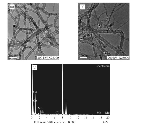 Figure 2.
TEM images of (a) CNT, (b) S-CoMo/CNT, and (c) EDX of CoMo/CNT
Figure 2.
TEM images of (a) CNT, (b) S-CoMo/CNT, and (c) EDX of CoMo/CNT
2.3 Textural characteristics of CoMo/CNT
The physical adsorption-desorption isotherms of N2 at -196 ℃ for pure CNT and CoMoS/CNT catalysts are shown in Figure 3(a). The isotherm corresponding to type IV is obtained for the pure CNT indicating the presence of mesopores. Figure 3(b) shows the pore size distribution (PSD) calculated by the BJH method. The pretreated CNT and CoMoS/CNT PSD have the average pore size of about 12 and 18 nm respectively. The specific surface area and pore volume data of CNT and CoMoS/CNT are listed in Table 2. The pure and metal loaded alumina samples show relatively higher ABET values than the corresponding CNT samples. After metal impregnation, for all samples, a consistent decrease in the ABET and average pore diameter are observed. The decline of the surface area and pore size may due to the blocking of some microspores and surface smoothing by the metal deposition on the support. Thus, metal loading has a great effect in decreasing textural characteristics of catalyst.
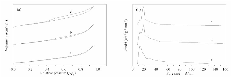 Figure 3.
N2 adsorption/desorption isotherm (a) and particle size distribution (b) exhibited for pure catalyst
Table 2.
Physical properties of supports and CoMoX/support catalysts
Figure 3.
N2 adsorption/desorption isotherm (a) and particle size distribution (b) exhibited for pure catalyst
Table 2.
Physical properties of supports and CoMoX/support catalysts
Sample BET surface area A/(m2·g-1) Total pore volume v/(cm3·g-1) Average pore diameter d/nm CNT 120.9 0.25 38.02 CoMo/CNT 101.1 0.18 35.28 CoMoS/CNT 73.58 0.12 32.57 γ-Al2O3 137.2 0.19 27.7 CoMo/ γ-Al2O3 113.3 0.16 28.8 CoMoS/ γ-Al2O3 66.9 0.1 32.1 Table 2. Physical properties of supports and CoMoX/support catalysts2.4 Raman spectroscopy
Figure 4 presents the Raman spectra for the supplied CNTs, CoMoO4/CNT and sulfided catalyst. The pure CNT spectrum (Figure 4(a)) displays two main intense peaks around 1 343 and 1 575 cm-1. The peak at 1 343 cm-1, known as the D-band, is due to the disordered carbon[35]. The second peak, referred as G band, is attributed to the highly graphitized CNT. It is known that the D to G band relative intensity indicates the quality and purity of the produced CNTs. The lower intensity ratio of ID/IG proves the higher degree of graphitization and purity of the CNTs[36]. The obtained low ID/IG ratio of 0.22 form the pure CNT spectra implies the very high CNTs graphitization degree. Clearly, these results are in a good agreement with the XRD and TEM results (Figures 1 and 2).
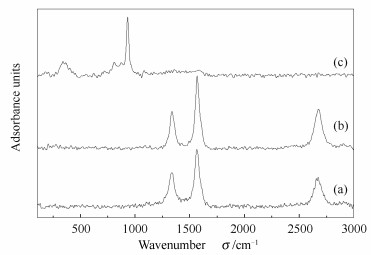 Figure 4.
Laser Raman spectra of (a) CNT, (b) CoMoO/CNT, (c) S-CoMo/CNT
Figure 4.
Laser Raman spectra of (a) CNT, (b) CoMoO/CNT, (c) S-CoMo/CNT
The CoMoO4/CNT Raman spectra (Figure 4(b)) show only the peaks of the pure CNT. This observation may be due to the good dispersion of loaded metal oxides over the carbon nanotubes. The CoMoS/CNT catalyst Raman spectrum is shown in Figure 4(c). The catalyst exhibits a band at 335 cm-1 and a large sharp peak at 940 cm-1 that can be attributed to the symmetric Mo=O stretching of tetrahedral MoO42-[22]. This result proves the higher dispersion of Mo due to the low Mo-CNT interaction. Moreover, none of the known peaks for polymeric molybdates, bulk CoMoO4 or bulk Co or Mo are recorded. The literatures state that the bands at about 320 and 920 cm-1 are assigned for the monomeric Mo species while bands at about 220, 360 and 960 cm-1 are ascribed to the well-dispersed octamolybdates[37]. Additionally, the bands at ca. 820, 945 and 952 cm-1 are attributed to the bulk CoMoO4. While, the characteristic bands of bulk Co and Mo oxides are usually known to be at 696 and 820 cm-1 respectively[22, 38].
2.5 Catalytic activity
2.5.1 Effect of reaction temperature
Table 3 represents the effect of reaction temperature on the product quality. It is shown that yield of heavy vacuum gas oil (HVGO) is clearly affected by the reaction temperature. The liquid yields of the CoMoS/CNT catalyst decrease with the temperature due to the increasing in reaction severity. As a result, the hydrodesulfrization (HDS) activities of the CoMoS/CNT catalyst increase continuously from 61.4% to 79.26% at temperature from 325 to 375 ℃ under constant reaction conditions of 4 MPa pressure for 2 h reaction time. Also, Table 3 demonstrates the effects of temperature on aniline point and diesel index (DI). Normally, these properties give an indication on the hydrogenation activity of the CoMoS/CNT catalyst. From the table it can be seen that as the reaction temperature increasing from 325 to 375 ℃ the aromatic contents decrease from 25% to 17.6%, and the total saturates contents increase from 75% to 82.4%. This is due to the hydrogenation of aromatics which is an exothermic reaction and is favored at low reaction temperature[39].
Table 3.
Effect of reaction temperature on hydrotreating of HVGO by CoMoS/CNT at p=4 MPa, t=2 h and C/F=1:75
Characteristy Feed 325 ℃ 350 ℃ 375 ℃ CNT alumina CNT alumina CNT alumina Total liquid yield w/% - 83.66 82 78 80 54 75.66 Total sulfur content w/% 1.66 0.64 0.82 0.38 0.76 0.34 0.61 Sulfur reduction (HDS) /% - 61.4 50.6 77.1 54.21 79.26 63.25 Aniline point /°F 165.2 170.24 166.28 170.6 167 171.32 168.26 Diesel index (DI) /% 46.09 57.37 53.64 59.65 55.1 60.56 55.57 Total aromatics w/% 34 25 29 21.5 26.5 17.6 25 Hydrodearomatization (HDA) w/% - 26.47 14.7 36.76 22.05 48.23 26.47 Table 3. Effect of reaction temperature on hydrotreating of HVGO by CoMoS/CNT at p=4 MPa, t=2 h and C/F=1:75Hydrotreating results for both catalysts show that alumina based catalysts produce higher oil product but with lower valuable properties. The CoMoS/CNT catalyst with HDS of 77% produces almost the half sulfur content value than the alumina based catalyst with HDS of only 54% at 350 ℃. Also, the CoMoS/CNT reduces aromatics content by around 9% more than the alumina catalyst. More over the CNT based catalyst improves the diesel index and aniline point by 4% and 3 degrees respectively.
From Table 3 it is clear that CoMoS/CNT catalyst has a higher catalytic activity than the alumina supported catalyst at the same reaction conditions. This behavior clearly cannot be explained on the bases of the reaction condition since both catalysts had investigated at the same conditions. Considering both catalysts texture properties and particle size (Table 2) it is clear that the alumina supported catalysts have higher ABET than the corresponding CNT supported catalysts which may have a revers catalytic behavior. Another factor that may be considered is the type of active phase formed during the catalysts preparation method.
This behavior may be explained by the good metal distribution over the CNT surface. On the other hand, the formation of MoO2 species, as can be indicated from the XRD and Raman analyses, is favorable on the CNT based catalyst surface. In contrary, over the alumina supported catalyst the MoO3 species is formed which is difficult to be sulfided and act as active phase for high activity. Furthermore, the normal Mo-Al2O3 interactions hinder the sulfiding process and prohibit the Co-Mo interaction and decrease the Co promotion effect. All the above mentioned reasons can support the higher catalytic activity demonstrated by the CoMoS/CNT catalyst.
2.5.4 Effect of catalyst/oil ratio
The amount of catalyst is also very important for hydrotreating process. Figure 5 shows the effect of weight of catalyst on the HDS of heavy gas oil.
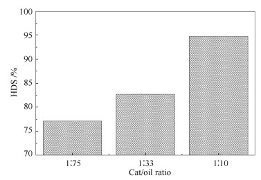 Figure 5.
Effect of catalyst/oil ratio of CoMoS/CNT on HVGO at 4 MPa, 350 ℃, 2 h
Figure 5.
Effect of catalyst/oil ratio of CoMoS/CNT on HVGO at 4 MPa, 350 ℃, 2 h
When the amount of catalyst is 2 g the HDS reaches 77.1% due to the absence of enough active sites for the reaction with the least amount of catalyst. With farther increase the weight of catalyst to 4.54 and 15 g the HDS increase to 82.7% and 94.8% respectively, due to the increased in the amount of catalyst and hence the increase in the number of acid sites available. The presence of more active sites will allow a much further hydrogen and oil to be adsorbed and hence influence the activity.
2.5.3 Effect of time
Table 5 represents the effect of time on the product quality of HVGO. The hydrogenation function of the catalyst increases due to the increase in the contact time between the reacting HVGO molecules and the acid hydrogenation sites of the catalyst. As a result the HDS activity of the catalyst increased from 77.1% to 83.1%, and the improvement of color, total aromatics content, aniline point and diesel index are observed. This means that improvement in the quality of heavy vacuum gas oil by increasing time from 2 to 6 h.
Table 5.
Effect of reaction time on hydrotreating of HVGO by /CNT at p=40 MPa, t=350 ℃ and C/ F ratio=1:75
Characteristy Feed 2 h 4 h 6 h Total liquid yield w/% 150 78 75.33 69.2 Total sulfur content w/% 1.66 0.38 0.36 0.28 Sulfur reduction (HDS) /% - 77.1 78.3 83.1 Aniline point /°F 165.2 170.6 170.96 172.04 Total aromatics w/% 34 21.5 18 16 Hydrodearomatization (HDA) w/% - 36.76 47.05 52.94 Table 5. Effect of reaction time on hydrotreating of HVGO by /CNT at p=40 MPa, t=350 ℃ and C/ F ratio=1:752.5.2 Effect of hydrogen pressure
Results of hydrogen pressure effects are shown in Table 4. As the initial hydrogen pressures increase from 2 to 6 MPa, the HDS increases from 60.24% to 79.5%, DI and aniline point increase from 56.59% to 61.18% and 169.7°F to 172.4°F respectively, while total aromatics contents decrease from 24% to 16.8 %, which can be attributed to the increase of hydrogenation activity of the catalyst with increasing total hydrogen pressure besides the increase of saturation activity and reduction of coke formation[39, 40].
Table 4.
Effect of reaction pressure on hydrotreating of HVGO by CoMoS/CNT at t=350 ℃, t=2 h and C/F=1:75
Characteristics Feed 2 MPa 4 MPa 6 MPa Total liquid yield w/% 150 85.33 78 72 Total sulfur content w/% 1.66 0.66 0.38 0.34 Sulfur reduction (HDS) /% - 60.24 77.1 79.5 Aniline point /°F 165.2 169.7 170.6 172.4 Total aromatics w/% 34 24 21.5 16.8 Hydrodearomatization (HDA) w/% - 29.41 36.76 50.58 Table 4. Effect of reaction pressure on hydrotreating of HVGO by CoMoS/CNT at t=350 ℃, t=2 h and C/F=1:753 Conclusions
The CoMoS/CNT hydrotreating catalyst is prepared by impregnation method. The TEM analysis shows that purified CNTs prove their morphological and structural features. Additionally, TEM indicates a good dispersion of Mo species and uniform Co particles deposition over the CNTs surface.
The catalyst, with 12% Mo loading and 0.7 Co/Mo atomic ratios supported on CNT, exhibits an excellent catalytic performance towards hydrotreating process under the experimental conditions. Consequently, the desired promoted Co-Mo-S phase formation upon sulfidation process is confirmed. The high catalytic performance of CoMoS/CNT can be achieved at low operating condition of 350 ℃, 40 bar and catalyst/ratio of 1:10 for 2 h. A fairly high HDS of 77.1% can be achieved over a low catalyst to oil ratio of 1:75 (g/g). The CoMoS/CNT catalyst shows a higher catalytic activity than CoMoS/γ-Al2O3.
-
-
[1]
TOPSФE H, CLAUSEN B S. Importance of Co-Mo-S type structures in hydrodesulfurization[J]. Catal Rev Sci Eng, 1984, 26(3/4): 395-420.
-
[2]
PRINS R, DE BEER V H J, SOMORJAI G A. Structure and function of the catalyst and the promoter in Co-Mo hydrodesulfurization catalysts[J]. Catal Rev Sci Eng, 1989, 31(1/2): 1-41.
-
[3]
MEDICI L, PRINS R. The influence of chelating ligands on the sulfidation of Ni and Mo in NiMo/SiO2 hydrotreating catalysts[J]. J Catal, 1996, 163(1): 38-49. doi: 10.1006/jcat.1996.0303
-
[4]
SHIMIZU T, HIROSHIMA K, HONMA T, MOCHIZUKI T, YAMADA M. Highly active hydrotreatment catalysts prepared with chelating agents[J]. Catal today, 1998, 45(1/4): 271-276.
-
[5]
VAN LOOIJ F, VAN DER LAAN P, STORK W H J, DICAMILLO D J, SWAIN J. Key parameters in deep hydrodesulfurization of diesel fuel[J]. Appl Catal A: Gen, 1998, 170(1): 1-12. doi: 10.1016/S0926-860X(98)00028-3
-
[6]
SHIMADA H, SATO T, YOSHIMURA Y, HIRAISHI J, NISHIJIMA A. Support effect on the catalytic activity and properties of sulfided molybdenum catalysts[J]. J Catal, 1988, 110(2): 275-284. doi: 10.1016/0021-9517(88)90319-3
-
[7]
VISHWAKARMA S K. Sonochemical and impregnated Co-W/γ-Al2O3 catalysts: Performances and kinetic studies on hydrotreatment of light gas oil[D].Saskatoon University of Saskatchewan, 2007.
-
[8]
TOPSФE H, CLAUSEN B S. Active sites and support effects in hydrodesulfurization catalysts[J]. Appl Catal, 1986, 25(1/2): 273-293.
-
[9]
ESWARAMOORTHI I, SUNDARAMURTHY V, DAS N, DALAI A K, ADJAYE J. Application of multi-walled carbon nanotubes as efficient support to NiMo hydrotreating catalyst[J]. Appl Catal A: Gen, 2008, 339(2): 187-195. doi: 10.1016/j.apcata.2008.01.021
-
[10]
SIGURDSON S, SUNDARAMURTHY V, DALAI A K, ADJAYE J. Effect of anodic alumina pore diameter variation on template-initiated synthesis of carbon nanotube catalyst supports[J]. JMol Catal A: Chem, 2009, 306: 23-32. doi: 10.1016/j.molcata.2009.02.016
-
[11]
DHAR G M, SRINIVAS B N, RANA M S, KUMAR M, MAITY S K. Mixed oxide supported hydrodesulfurization catalysts-A review[J]. Catal Today, 2003, 86(1/4): 45-60.
-
[12]
WANG A, WANG Y, KABE T, CHEN Y, ISHIHARA A, QIAN W. Hydrodesulfurization of dibenzothiophene over siliceous MCM-41-supported catalysts: I. Sulfided Co-Mo catalysts[J]. J Catal, 2001, 199(1): 19-29. doi: 10.1006/jcat.2000.3148
-
[13]
MAITY S K, RANA M S, BEJ S K, ANCHEYTA-JUAREZ J, DHAR G M, RAO T S R P. Studies on physico-chemical characterization and catalysis on high surface area titania supported molybdenum hydrotreating catalysts[J]. Appl CatalA: Gen, 2001, 205(1/2): 215-225.
-
[14]
VRADMAN L, LANDAU M V, HERSKOWITZ M, EZERSKY V, TALIANKER M, NIKITENKO S, KOLTYPIN Y, GEDANKEN A. High loading of short WS 2 slabs inside SBA-15: Promotion with nickel and performance in hydrodesulfurization and hydrogenation[J]. J Catal, 2003, 213(2): 163-175. doi: 10.1016/S0021-9517(02)00012-X
-
[15]
POUR A N, RASHIDI A M, JOZANI K J, MOHAJERI A, KHORAMI P. Support effects on the chemical property and catalytic activity of Co-Mo HDS catalyst in sulfur recovery[J]. J Nat Gas Chem, 2010, 19(1): 91-95. doi: 10.1016/S1003-9953(09)60032-3
-
[16]
SERP P, CORRIAS M, KALCK P. Carbon nanotubes and nanofibers in catalysis[J]. Appl Catal A: Gen, 2003, 253: 337-358. doi: 10.1016/S0926-860X(03)00549-0
-
[17]
VAN STEEN E, PRINSLOO F F. Comparison of preparation methods for carbon nanotubes supported iron Fischer-Tropsch catalysts[J]. Catal Today, 2002, 71(3/4): 327-334.
-
[18]
AUER E, FREUND A, PIETSCH J, TACKE T. Carbons as supports for industrial precious metal catalysts[J]. Appl Catal A: Gen, 1998, 173(2): 259-271. doi: 10.1016/S0926-860X(98)00184-7
-
[19]
SHANG H Y, LIU C G, XU Y Q, ZHAO H J, SONG H H. Effect of the surface modification of multi-walled carbon nanotubes (MWCNTs) on hydrodesulfurization activity of Co-Mo/MWCNTs catalysts[J]. New Carbon Mater, 2004, 19(2): 131-136.
-
[20]
KYOTANI T, NAKAZAKI S, XU W-H, TOMITA A. Chemical modification of the inner walls of carbon nanotubes by HNO3 oxidation[J]. Carbon, 2001, 39(5): 782-785. doi: 10.1016/S0008-6223(01)00013-6
-
[21]
DONG K, ZHANG S, WANG D, YAO X. Hydrogen bonds in imidazolium ionic liquids[J]. J Phys Chem A, 2006, 110(31): 9775-9782. doi: 10.1021/jp054054c
-
[22]
SHANG H, LIU C, XU Y, QIU J, WEI F. States of carbon nanotube supported Mo-based HDS catalysts[J]. Fuel Process Technol, 2007, 88(2): 117-123. doi: 10.1016/j.fuproc.2004.08.010
-
[23]
AWADALLAH A E, ABOUL-ENEIN A A, EL-DESOUKI D S, ABOUL-GHEIT A K. Catalytic thermal decomposition of methane to COx-free hydrogen and carbon nanotubes over MgO supported bimetallic group Ⅷ catalysts[J]. ApplSurfSci, 2014, 296: 100-107.
-
[24]
SUNDARAMURTHY V, DALAI A K, ADJAYE J. Effect of EDTA on hydrotreating activity of CoMo/γ-Al2O3 catalyst[J]. CatalLett, 2005, 102(3): 299-306.
-
[25]
HOGG J C, CHU F, UTOKAPARCH S, WOODS R, ELLIOTT W M, BUZATU L, CHERNIACK R M, ROGERS R M, SCIURBA F C, COXSON H O, PARP D. The nature of small-airway obstruction in chronic obstructive pulmonary disease[J]. N Engl J Med, 2004, 350: 2645-2653. doi: 10.1056/NEJMoa032158
-
[26]
SHIGAPOV A N, GRAHAM G W, MCCABE R W, PECK M P, PLUMMER H K. The preparation of high-surface-area cordierite monolith by acid treatment[J]. Appl Catal A: Gen, 1999, 182(1): 137-146. doi: 10.1016/S0926-860X(99)00003-4
-
[27]
TAN Z L, XIAO H N, ZHANG R D, ZHANG Z S, KALIAGUINE S. Potential to use mesoporous carbon as catalyst support for hydrodesulfurization[J]. New Carbon Mater, 2009, 24(4): 333-343. doi: 10.1016/S1872-5805(08)60056-6
-
[28]
ZHANG Y, ZHANG H B, LIN G D, CHEN P, YUAN Y Z, TSAI K R. Preparation, characterization and catalytic hydroformylation properties of carbon nanotubes-supported Rh-phosphine catalyst[J]. Appl Catal A: Gen, 1999, 187(2): 213-224. doi: 10.1016/S0926-860X(99)00229-X
-
[29]
DUJARDIN E, EBBESEN T W, HIURA H, TANIGAKI K. Capillarity and wetting of carbon nanotubes[J]. Science, 1994, 265(5180): 1850-1852. doi: 10.1126/science.265.5180.1850
-
[30]
DANDEKAR A, BAKER R T K, VANNICE M A. Characterization of activated carbon, graphitized carbon fibers and synthetic diamond powder using TPD and DRIFTS[J]. Carbon, 1998, 36(12): 1821-1831. doi: 10.1016/S0008-6223(98)00154-7
-
[31]
KARIMI A, NASERNEJAD B, RASHIDI A M. Synthesis and characterization of multiwall carbon nanotubes/alumina nanohybrid-supported cobalt catalyst in Fischer-Tropsch synthesis[J]. J Energy Chem, 2013, 22(4): 582-590. doi: 10.1016/S2095-4956(13)60076-5
-
[32]
TRÉPANIER M, TAVASOLI A, DALAI AK, ABATZOGLOU N. Fischer-Tropsch synthesis over carbon nanotubes supported cobalt catalysts in a fixed bed reactor: Influence of acid treatment[J]. Fuel Process Technol, 2009, 90(3): 367-374. doi: 10.1016/j.fuproc.2008.10.012
-
[33]
KARIMI A, NASERNEJAD B, RASHIDI A M, TAVASOLI A, POURKHALIL M. Functional group effect on carbon nanotube (CNT)-supported cobalt catalysts in Fischer-Tropsch synthesis activity, selectivity and stability[J]. Fuel, 2014, 117: 1045-1051. doi: 10.1016/j.fuel.2013.10.014
-
[34]
ABBASLOU R M M, TAVASSOLI A, SOLTAN J, DALAI A K. Iron catalysts supported on carbon nanotubes for Fischerâ Tropsch synthesis: Effect of catalytic site position[J]. Appl Catal A: Gen, 2009, 367(1/2): 47-52.
-
[35]
DRESSELHAUS M S, DRESSELHAUS G, JORIO A, SOUZA FILHO A G, SAITO R. Raman spectroscopy on isolated single wall carbon nanotubes[J]. Carbon, 2002, 40(12): 2043-2061. doi: 10.1016/S0008-6223(02)00066-0
-
[36]
LI Q, YAN H, ZHANG J, LIU Z. Effect of hydrocarbons precursors on the formation of carbon nanotubes in chemical vapor deposition[J]. Carbon, 2004, 42(4): 829-835. doi: 10.1016/j.carbon.2004.01.070
-
[37]
KOHLER S D, EKERDT J G, KIM D S, WACHS I E. Relationship between structure and point of zero surface charge for molybdenum and tungsten oxides supported on alumina[J]. Catal Lett, 1992, 16(3): 231-239. doi: 10.1007/BF00764335
-
[38]
JEZIOROWSKI H, KNOZINGER H, GRANGE P, GAJARDO P. Raman spectra of cobalt molybdenum oxide supported on silica[J]. J Phys Chem, 1980, 84: 1825-1829. doi: 10.1021/j100451a017
-
[39]
GARY J H, HANDWERK G E, KAISER M J. Petroleum refining: Technology and economics[C]. Boca Raton: CRC Press, 2007.
-
[40]
BARTHOLOMEW C H. Catalyst deactivation in hydrotreating of residua: A review[C]. New York: Marcel Dekker, 1994.
-
[1]
-

Figure 1 XRD patterns of different samples
a: CNT; b: CoMoO/CNT; c: CoMoS/CNT; d: γ-Al2O3; e: CoMoO/γ-Al2O3; f: CoMoS/γ-Al2O3

Figure 3 N2 adsorption/desorption isotherm (a) and particle size distribution (b) exhibited for pure catalyst
a: CNT; b: CoMoO/CNT; c: CoMoS/CNT
Table 1. Properties of heavy vacuum gas oil feedstock
Experiment Method Result Total sulfur content w/% ASTM D-4294 1.66 Aniline point /°F ASTM D-611-82 74 Diesel index /% ASTM D 611 46.09 Total aromatics w/% - 34  下载: 导出CSV
Table 2. Physical properties of supports and CoMoX/support catalysts
Sample BET surface area A/(m2·g-1) Total pore volume v/(cm3·g-1) Average pore diameter d/nm CNT 120.9 0.25 38.02 CoMo/CNT 101.1 0.18 35.28 CoMoS/CNT 73.58 0.12 32.57 γ-Al2O3 137.2 0.19 27.7 CoMo/ γ-Al2O3 113.3 0.16 28.8 CoMoS/ γ-Al2O3 66.9 0.1 32.1
下载: 导出CSV
Table 3. Effect of reaction temperature on hydrotreating of HVGO by CoMoS/CNT at p=4 MPa, t=2 h and C/F=1:75
Characteristy Feed 325 ℃ 350 ℃ 375 ℃ CNT alumina CNT alumina CNT alumina Total liquid yield w/% - 83.66 82 78 80 54 75.66 Total sulfur content w/% 1.66 0.64 0.82 0.38 0.76 0.34 0.61 Sulfur reduction (HDS) /% - 61.4 50.6 77.1 54.21 79.26 63.25 Aniline point /°F 165.2 170.24 166.28 170.6 167 171.32 168.26 Diesel index (DI) /% 46.09 57.37 53.64 59.65 55.1 60.56 55.57 Total aromatics w/% 34 25 29 21.5 26.5 17.6 25 Hydrodearomatization (HDA) w/% - 26.47 14.7 36.76 22.05 48.23 26.47
下载: 导出CSV
Table 4. Effect of reaction pressure on hydrotreating of HVGO by CoMoS/CNT at t=350 ℃, t=2 h and C/F=1:75
Characteristics Feed 2 MPa 4 MPa 6 MPa Total liquid yield w/% 150 85.33 78 72 Total sulfur content w/% 1.66 0.66 0.38 0.34 Sulfur reduction (HDS) /% - 60.24 77.1 79.5 Aniline point /°F 165.2 169.7 170.6 172.4 Total aromatics w/% 34 24 21.5 16.8 Hydrodearomatization (HDA) w/% - 29.41 36.76 50.58
下载: 导出CSV
Table 5. Effect of reaction time on hydrotreating of HVGO by /CNT at p=40 MPa, t=350 ℃ and C/ F ratio=1:75
Characteristy Feed 2 h 4 h 6 h Total liquid yield w/% 150 78 75.33 69.2 Total sulfur content w/% 1.66 0.38 0.36 0.28 Sulfur reduction (HDS) /% - 77.1 78.3 83.1 Aniline point /°F 165.2 170.6 170.96 172.04 Total aromatics w/% 34 21.5 18 16 Hydrodearomatization (HDA) w/% - 36.76 47.05 52.94
下载: 导出CSV
-


 扫一扫看文章
计量
- PDF下载量: 0
- 文章访问数: 0
- HTML全文浏览量: 0
 下载:
下载: